USER MANUAL · v1.4 · ENGLISH
Neutron
Operating instructions and configuration
1. MANUAL VERSIONS
| Version | Description of change |
|---|---|
| 1 – January 2026 | First Neutron manual release. |
| 1.2. – March 2026 | Added HTTPS support. |
| 1.3. – May 2026 | Added how to connect with typical wiring examples |
| 1.4. – July 2026 | Firmware version >= 1.7 Scale communication interface supports multiple communication interfaces for scale communication – see section 7.1 Firmware version >= 1.8 Added section for Modbus RTU (see section 10.3) and TCP (see section 16.4) Firmware version >=1.8.3 WIFI country of use selection – see section 8.7 WIFI transmit power can now be adjusted – see section 8.8 |
View original page 5 — diagrams and layout
2. DESCRIPTION
This manual describes the operation and features of the Neutron hybrid module .
The term HYBRID means that Neutron can operate in two distinct modes:
CloudScaleLink Mode (Communication-Only Mode)
In this mode, Neutron works solely as a CloudScaleLink interface , allowing you to connect any existing weighing scale or other device to Scale Monitor using:
- UART / RS-232 • RS-485
Expanded Mode with IO Board
By attaching the IO board, you unlock additional hardware features, including:
- 4-channel weighing system with a 24-bit ADC capable of up to 4,800 conversions per second • 6 digital inputs • 6 digital outputs
Neutron’s modular design also supports multiple connectivity options. Bluetooth BLE and Wi-Fi are included as standard, while Ethernet connectivity can be added using an addon.
In this manual, you will become familiar with all available connectivity options and the full set of functions offered by the Neutron hybrid module.
View original page 6 — diagrams and layout
3. TECHNICAL SPECIFICATIONS
3.1. CPU BOARD SPECIFICATIONS
| Power supply | 5-24Vdc ± 5% | Typical consumption at 5Vdc: 80 mA with WIFI only (peak 100 mA; scanning WIFI). With Ethernet addon typical is consumption 170 mA at 5Vdc (peak 250 mA). |
|---|---|---|
| Serial ports | UART/RS-232: switchable between UART and RS-232 by using SW1 on board RS-232 maximum distance: up to 15 meters | Baud rates: 1200, 2400, 4800, 9600, 19200, 38400, 57600, 115200 bps Data bits: 7 or 8 Parity: none, even, odd |
| RS-485: yes with address configuration from 0-255; maximum allowed distance: 1200 m with shielded 2 x 24AWG twisted pair with outer braid + aluminium strip | ||
| Bluetooth LE | Bluetooth BLE 5.0 | Supports Bluetooth to bidirectional serial redirection to UART/RS-232 or RS- 485 port |
| Wi-Fi | 2.4 GHz Wi-Fi (IEEE 802.11b/g/n) Range: up to 50 m indoor up to 150 m outdoor | Supported encryptions: None WPA2-PSK WPA3-PSK WPA2-Enterprise (EAP-TLS, EAP-TTLS) WPA3-Enterprise (EAP-TLS, EAP-TTLS) |
| Ethernet (optional – product code CS- NA-ETH) | 10BaseT/100BaseTX Mb/s | Support Auto Negotiation (Full and half duplex, 10 and 100-based) LED outputs (Full/Half duplex, Link, Speed, Active) |
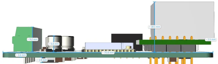
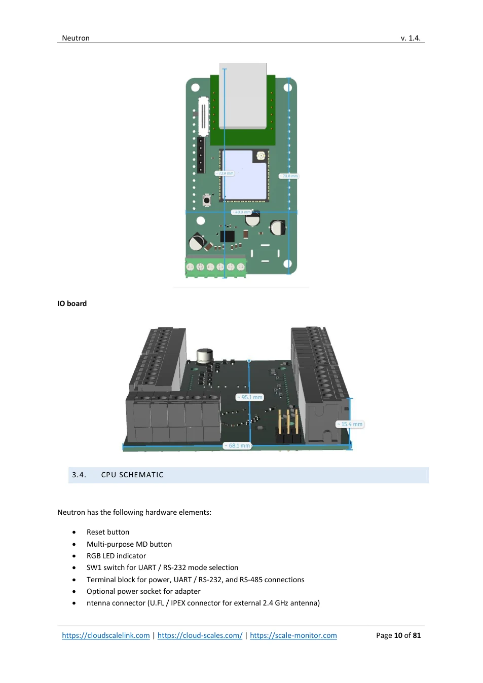
| Dimensions | 71x40x14 mm (without Ethernet) LxWxH 74x40x22 mm (with Ethernet) LxWxH | |
| Temperature range | -10 ~ +40 °C | |
| Humidity | Max 85% non-condensing |
3.2. IO BOARD SPECIFICATIONS
IO board extends Neutron features by adding 4 channel scale and opto-isolated six digital inputs and six fotomosfet outputs.
Power supply Directly from CPU board, no need for additional supply
View original page 7 — diagrams and layout
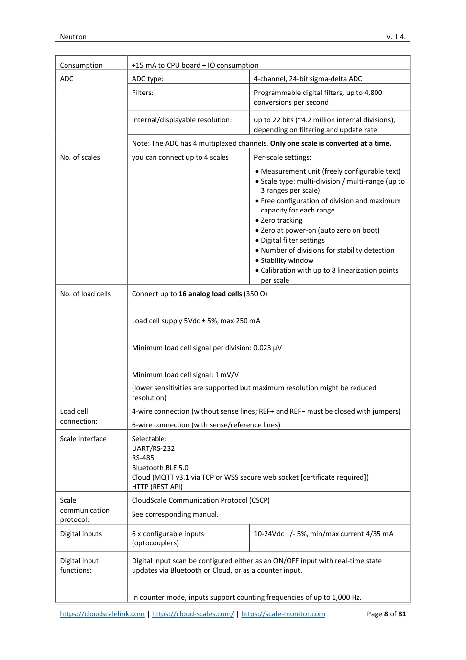
| Consumption | +15 mA to CPU board + IO consumption | |
|---|---|---|
| ADC | ADC type: | 4-channel, 24-bit sigma-delta ADC |
| Filters: | Programmable digital filters, up to 4,800 conversions per second | |
| Internal/displayable resolution: | up to 22 bits (~4.2 million internal divisions), depending on filtering and update rate | |
| Note: The ADC has 4 multiplexed channels. Only one scale is converted at a time. | ||
| No. of scales | you can connect up to 4 scales | Per-scale settings: • Measurement unit (freely configurable text) • Scale type: multi-division / multi-range (up to 3 ranges per scale) • Free configuration of division and maximum capacity for each range • Zero tracking • Zero at power-on (auto zero on boot) • Digital filter settings • Number of divisions for stability detection • Stability window • Calibration with up to 8 linearization points per scale |
| No. of load cells | Connect up to 16 analog load cells (350 Ω) Load cell supply 5Vdc ± 5%, max 250 mA Minimum load cell signal per division: 0.023 μV Minimum load cell signal: 1 mV/V (lower sensitivities are supported but maximum resolution might be reduced resolution) | |
| Load cell connection: | 4-wire connection (without sense lines; REF+ and REF− must be closed with jumpers) 6-wire connection (with sense/reference lines) | |
| Scale interface | Selectable: UART/RS-232 RS-485 Bluetooth BLE 5.0 Cloud (MQTT v3.1 via TCP or WSS secure web socket [certificate required]) HTTP (REST API) | |
| Scale communication protocol: | CloudScale Communication Protocol (CSCP) See corresponding manual. | |
| Digital inputs | 6 x configurable inputs (optocouplers) | 10-24Vdc +/- 5%, min/max current 4/35 mA |
| Digital input functions: | Digital input scan be configured either as an ON/OFF input with real-time state updates via Bluetooth or Cloud, or as a counter input. In counter mode, inputs support counting frequencies of up to 1,000 Hz. | |
View original page 8 — diagrams and layout
| Counter values are reported at a fixed update interval of 5 seconds. The maximum supported counter value is 18.4 billion (2^64 − 1). The current input state or counter value can be requested at any time by sending a command. Counters can be freely set or reset. Note: Although any GPIO can be assigned as a counter input, Neutron is limited to four simultaneous active counters due to hardware constraints. Inputs can be used also for scale function such as zero, tare, etc. | ||
|---|---|---|
| Digital outputs | 6 x fotomosfet optocoupler outputs | 5-24Vdc, max current 150 mA |
| Digital outputs functions: | Digital output can be controlled via command sent via Bluetooth or cloud. Digital outputs can be controlled also via scale depending on the application for instance activated in tolerance, out of tolerance, quick dosing, slow dosing etc. | |
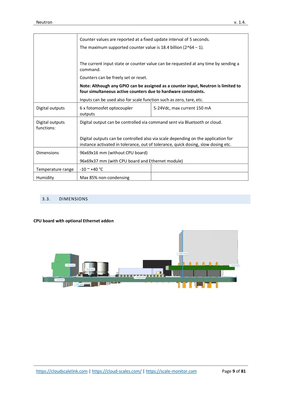
| Dimensions | 96x69x16 mm (without CPU board) 96x69x37 mm (with CPU board and Ethernet module) | |
| Temperature range | -10 ~ +40 °C | |
| Humidity | Max 85% non-condensing |
3.3. DIMENSIONS
CPU board with optional Ethernet addon
View original page 9 — diagrams and layout
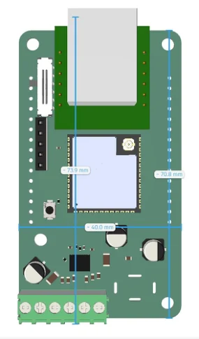
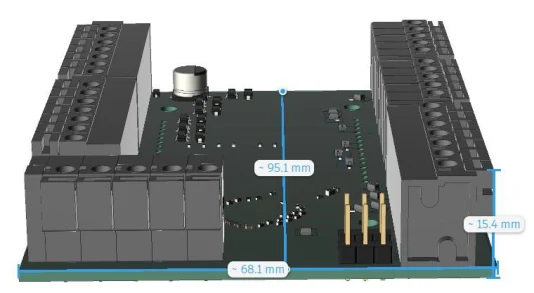
IO board
3.4. CPU SCHEMATIC
Neutron has the following hardware elements:
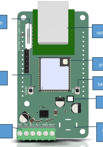
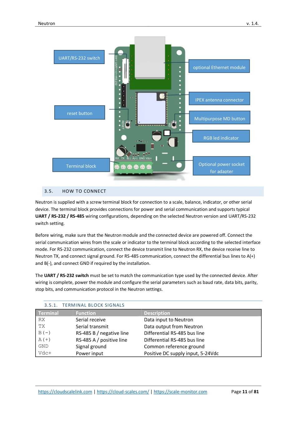
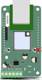
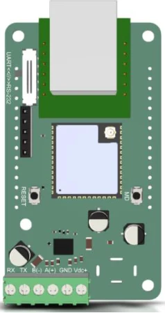
- Reset button • Multi-purpose MD button • RGB LED indicator • SW1 switch for UART / RS-232 mode selection • Terminal block for power, UART / RS-232, and RS-485 connections • Optional power socket for adapter • ntenna connector (U.FL / IPEX connector for external 2.4 GHz antenna)
View original page 10 — diagrams and layout
UART/RS-232 switch
optional Ethernet module
IPEX antenna connector
reset button
Multipurpose MD button
RGB led indicator
Terminal block Optional power socket
for adapter
3.5. HOW TO CONNECT
Neutron is supplied with a screw terminal block for connection to a scale, balance, indicator, or other serial device. The terminal block provides connections for power and serial communication and supports typical UART / RS-232 / RS-485 wiring configurations, depending on the selected Neutron version and UART/RS-232 switch setting.
Before wiring, make sure that the Neutron module and the connected device are powered off. Connect the serial communication wires from the scale or indicator to the terminal block according to the selected interface mode. For RS-232 communication, connect the device transmit line to Neutron RX, the device receive line to Neutron TX, and connect signal ground. For RS-485 communication, connect the differential bus lines to A(+) and B(-), and connect GND if required by the installation.
The UART / RS-232 switch must be set to match the communication type used by the connected device. After wiring is complete, power the module and configure the serial parameters such as baud rate, data bits, parity, stop bits, and communication protocol in the Neutron settings.
3.5.1. TERMINAL BLOCK SIGNALS
| Terminal | Function | Description | ||||||
|---|---|---|---|---|---|---|---|---|
| RX Serial receive Data input to Neutron TX Serial transmit Data output from Neutron B(-) RS-485 B / negative line Differential RS-485 bus line A(+) RS-485 A / positive line Differential RS-485 bus line GND Signal ground Common reference ground Vdc+ Power input Positive DC supply input, 5-24Vdc |
View original page 11 — diagrams and layout
3.5.2. TYPICAL WIRING EXAMPLES FOR UART, RS-232 AND RS-485 DEVICE
Always check the scale or indicator manual before wiring. Some manufacturers use different naming for RS-485 terminals, and A/B polarity may differ between devices. If communication does not work, verify baud rate and protocol settings first, then check TX/RX crossover for RS-232 or A/B polarity for RS-485.
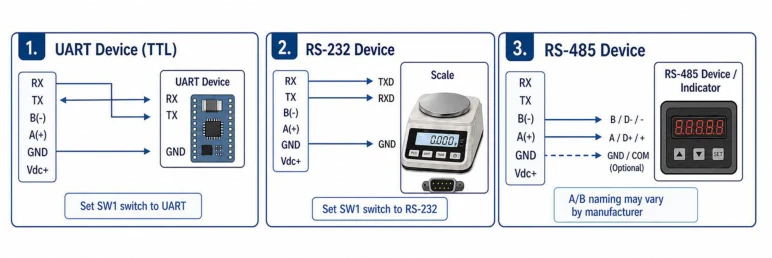

Always power off devices before wiring.
Vdc+ is the external DC power input for Neutron.
Check baud rate, parity and data bits after wiring. By default is: 9600 bps, none and 8 bits.
3.6. MD BUTTON
The MD button is a multi-purpose control button.
Each press is acknowledged by a blink of the RGB indicator.
Different functions are activated depending on the number of presses:
➢ 1 presses: soft restart of the module ➢ 2 presses: disable DHCP ➢ 3 presses: enable access point (see chapter 6.2) ➢ 4 presses: enable Bluetooth, if disabled. Bluetooth is enabled only until module is reboot. ➢ 5 presses: factory reset of the module
Note: MD button can be disabled in General settings of module.
View original page 12 — diagrams and layout
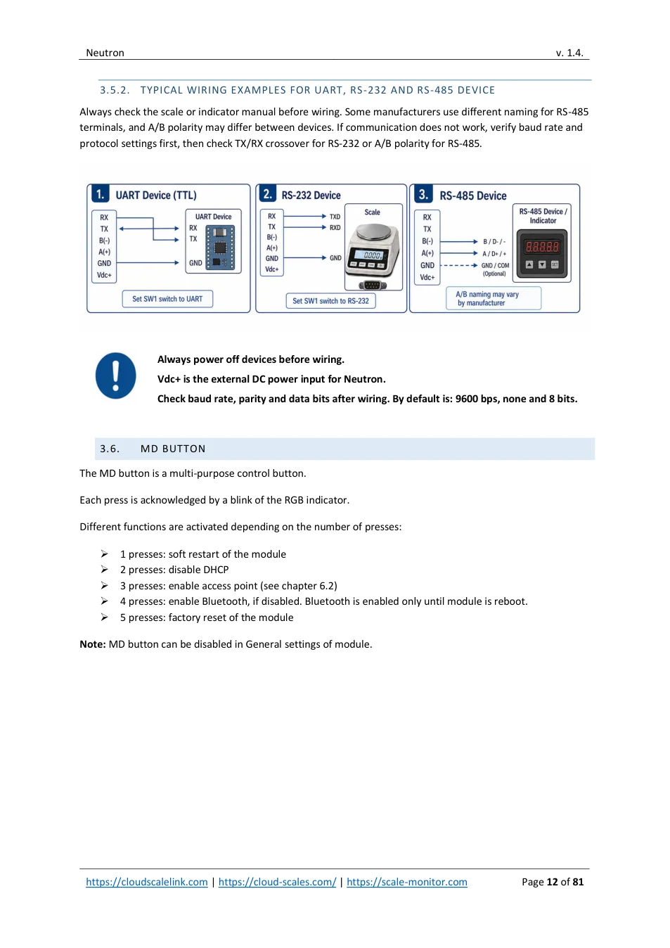
3.7. RGB LED INDICATOR
RGB led indicator provides simple overview of module state:
| RGB indicator colour | Wi-Fi connection | Ethernet connection | ||||||
|---|---|---|---|---|---|---|---|---|
| Green | Connected | Connected | ||||||
| Red | Not connected (no Wi-Fi available, signal to weak, etc.) | Not connected (no cable, Ethernet stopped, no module etc.) | ||||||
| Yellow | Connection failed (bad password, wrong encryption, etc.) | Connected but waiting for IP (only in case DHCP is enabled) | ||||||
| Gray | Wi-Fi disconnected | Lost IP Ethernet IP address lost | ||||||
| Orange | Unknown Wi-Fi status | Cable disconnected | ||||||
| Blue | When blinking it means Bluetooth debug is activated and waiting for Bluetooth connection | |||||||
| Purple | When MD button is pressed. | |||||||
| Off | Module is not powered or not working MD button pressed |
View original page 13 — diagrams and layout
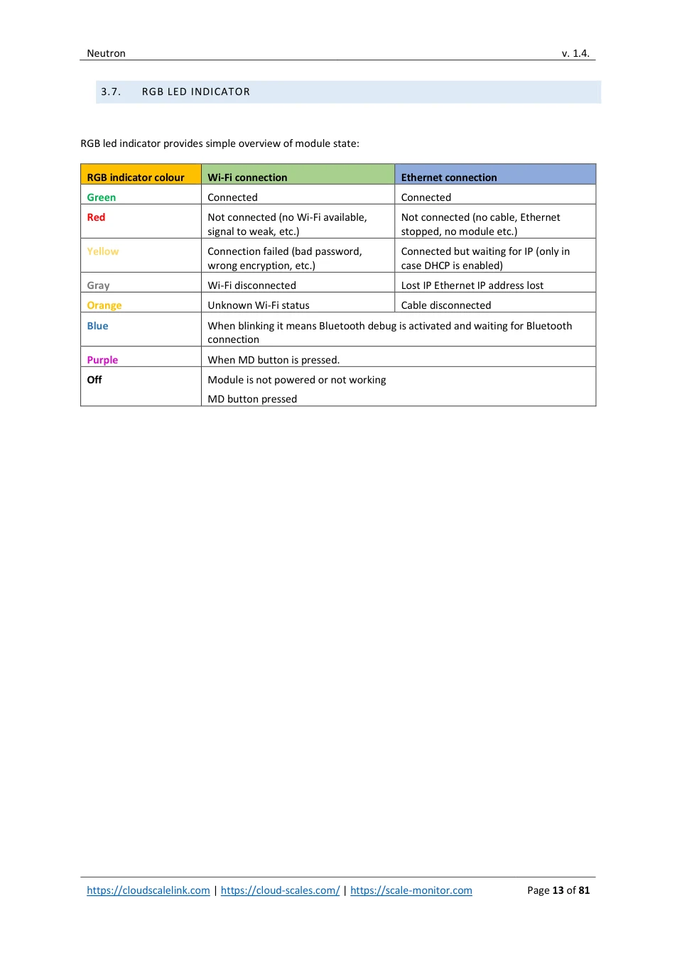
4. MODULE ID AND PIN
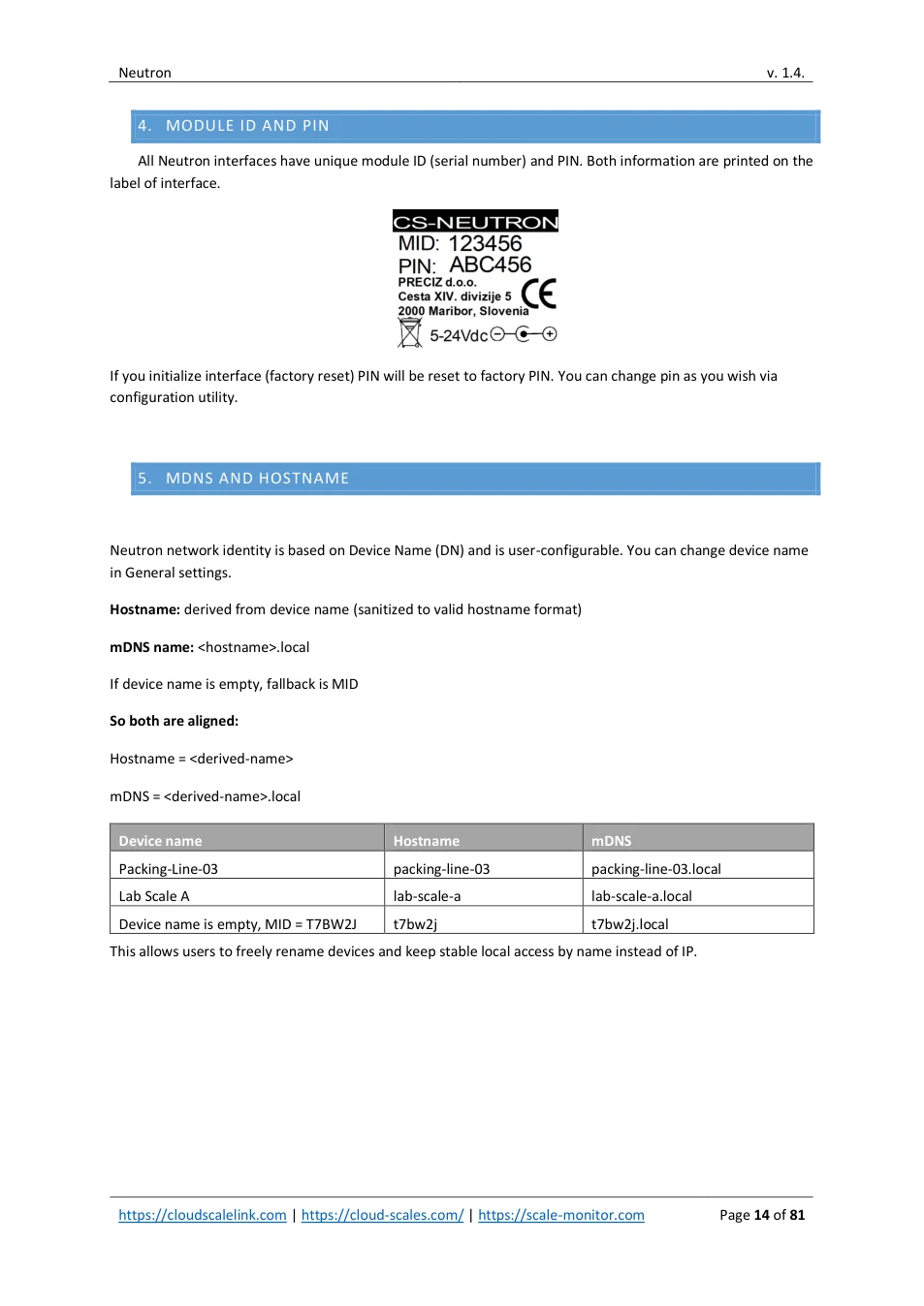
All Neutron interfaces have unique module ID (serial number) and PIN. Both information are printed on the label of interface.
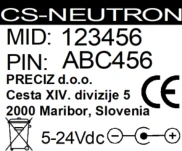
If you initialize interface (factory reset) PIN will be reset to factory PIN. You can change pin as you wish via configuration utility.
5. MDNS AND HOSTNAME
Neutron network identity is based on Device Name (DN) and is user-configurable. You can change device name in General settings.
Hostname: derived from device name (sanitized to valid hostname format)
mDNS name: <hostname>.local
If device name is empty, fallback is MID
So both are aligned:
Hostname = <derived-name>
mDNS = <derived-name>.local
| Device name | Hostname | mDNS | ||||||
|---|---|---|---|---|---|---|---|---|
| Packing-Line-03 | packing-line-03 | packing-line-03.local | ||||||
| Lab Scale A | lab-scale-a | lab-scale-a.local | ||||||
| Device name is empty, MID = T7BW2J | t7bw2j | t7bw2j.local |
This allows users to freely rename devices and keep stable local access by name instead of IP.
View original page 14 — diagrams and layout
6. CONFIGURATION UTILITIES
Neutron can be configured via four different configuration utilities.
| Utility | Interface | Platform | Accessible | ||||||||
|---|---|---|---|---|---|---|---|---|---|---|---|
| BLE | Bluetooth | Any, web based | https://apps.scale-monitor.com/ | ||||||||
| CMP – cloud | Wi-Fi, Ethernet internet connection required | Any, web based | https://login.scale-monitor.com/ | ||||||||
| management | |||||||||||
| platform | |||||||||||
| HTTP – internal web server | HTTP – internal | Wi-Fi, Ethernet LAN connection required | Any | http://192.168.4.1 (if connecting via WIFI access point) or http://ip address of module _ | |||||||
| web server | |||||||||||
| CSLTools | Wi-Fi, Ethernet LAN connection required | Windows only | https://apps.scale-monitor.com/ |
CMP – cloud management platform supports configuration of all module setting. Other configuration utilities might partially support configuration of Neutron. Each functionality has written under note in dedicated section, if configuration is not supported on any utility.
View original page 15 — diagrams and layout
7. COMMUNICATION INTERFACE
Neutron has Bluetooth and Wi-Fi interfaces enabled by default. These two interfaces are always available for basic communication and configuration.
Under General Settings you can select the communication interface used for internet and LAN access. You can choose either Wi-Fi or Ethernet.
If you do not want to use internet or LAN communication, you can disable the communication interface. In this case, Neutron will operate using Bluetooth only.
In this case you want to use Ethernet then, the Ethernet add-on module must be installed. If the Ethernet hardware is not present, the Ethernet option will not appear in the selection list.
7.1. MULTIPLE SCALE COMMUNICATION INTERFACES
Available with firmware version 1.7 or later
Neutron supports multiple communication interfaces for connection to a scale, PLC, computer, cloud service, or other external equipment.
The Scale communication interface setting allows the user to enable one or more communication interfaces at the same time. Each enabled interface can use its own selected communication protocol.
Depending on the installed hardware and firmware configuration, the following interfaces may be available:
- Bluetooth
- UART / RS-232
- RS-485
- TCP
- WebSocket
- HTTP / REST
- Cloud Scales / MQTT Cloud
- Modbus TCP
- Disabled
This makes it possible, for example, to use RS-232 for communication with an existing scale while simultaneously using Modbus TCP for PLC or SCADA integration, Bluetooth for local configuration, and Cloud communication for remote monitoring.
Selecting communication interfaces
1. Open the Neutron configuration utility.
2. Go to Scale communication interface .
3. Select the required interface or interfaces.
View original page 16 — diagrams and layout
4. Configure the communication protocol and parameters for each enabled interface.
5. Save the configuration and restart the communication service or reboot the module if requested.
Important: Only enable interfaces that are required by the installation. Unused communication interfaces should remain disabled to simplify configuration and reduce unnecessary network exposure.
Typical examples
| Application | Recommended interface configuration | ||||
|---|---|---|---|---|---|
| Scale Monitor Cloud + PC connection | RS-232 + Cloud Scales | ||||
| via RS-232/USB converter | |||||
| PLC or SCADA connection through | Modbus TCP | ||||
| Ethernet/Wi-Fi | |||||
| PLC connection through serial line | Modbus RTU via RS-232 or RS-485 | ||||
| Local mobile application | Bluetooth | ||||
| Integration with custom software | TCP, WebSocket or HTTP/REST |
Note: The available interfaces depend on the Neutron version, installed hardware options and selected firmware features. Ethernet-based functions require the optional Ethernet add-on where a wired Ethernet connection is used.
View original page 17 — diagrams and layout
8. WI-FI SETUP
In this section we will explain how to setup Wi-Fi connection.
8.1. QUICK WI-FI SETUP BY USING BLE BLUETOOTH UTILITY
The fastest way to connect Neutron to a Wi-Fi network is by using Bluetooth and BLE Configuration Utility. Open the following link on your smartphone, tablet, or PC (with Bluetooth support):

https://apps.scale-monitor.com/bleNeutron.html
Once the page is loaded, allow Bluetooth access and connect to your Neutron module.
NOTE: if you are using iPhone or iPad you will need to access above link via Bluefy web browser. Bluefy browser allows you to establish connection by using Bluetooth Low Energy.
Bluefy web browser is freely available in App store:
https://apps.apple.com/us/app/bluefy-web-ble-browser/id1492822055
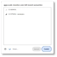
Step 1: Select Your Neutron Device
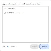
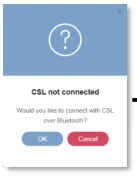
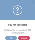
Once you confirm request for Bluetooth connection a list of available Neutron modules will appear. Select the Neutron you want to configure and click Pair.
→
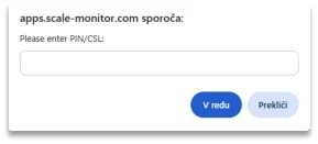
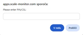
Step 2: Enter Neutron PIN
A new window will appear requesting the Neutron PIN code. Enter the PIN to establish a secure Bluetooth connection. Once connected, the status bar at the top will indicate your connection state:
- Green: connection established • Red: not connected
View original page 18 — diagrams and layout
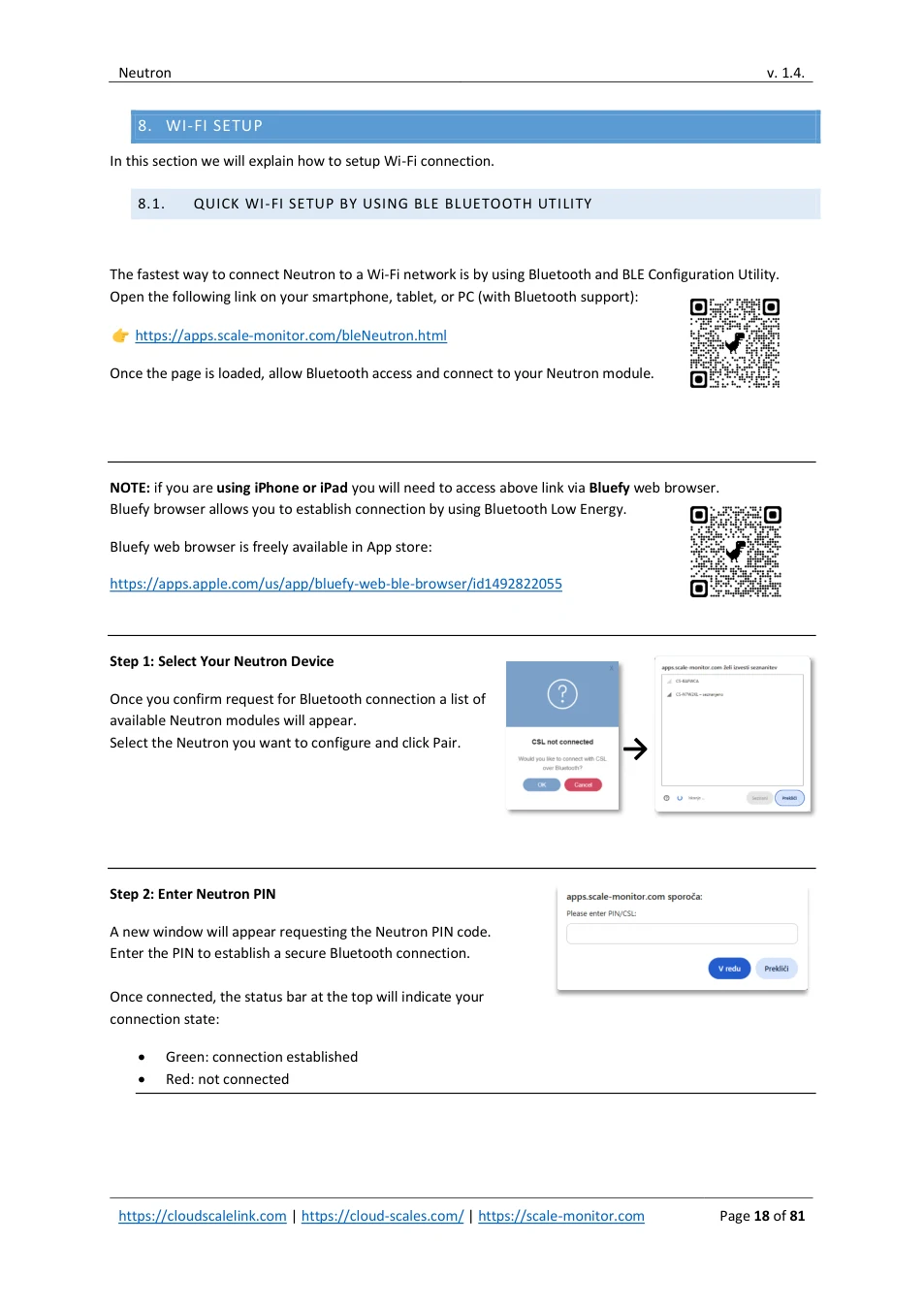
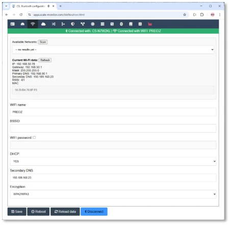
Step 3: Configure Wi-Fi Settings
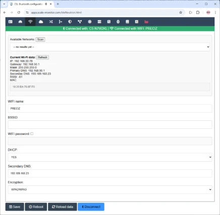
Click the Wi-Fi icon to open the wireless configuration page.
Fill in:
- Wi-Fi Name (SSID) • Wi-Fi Password
Click Save, wait for confirmation, then click Reboot to apply the new settings.
If the credentials are correct, Neutron will automatically connect to the Wi-Fi network after restarting.
8.2. QUICK WI-FI SETUP BY USING INTERNAL WEB SERVER (HTTP)
Neutron includes a built-in HTTP web server running on port 80.
This allows you to configure the module directly over Wi-Fi without using BLE.
Step 1: Enable Neutron Access Point
To activate the internal Wi-Fi Access Point (AP):

x 3
1. Press the MD button 43times. 2. Neutron will start broadcasting its own Wi-Fi network.
You can now connect to this AP from any phone, tablet, or computer.
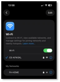
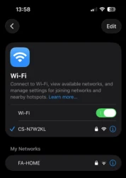
Step 2: Connect to the Neutron Wi-Fi Network
Open the Wi-Fi settings on your device and look for a network named:
CS-XXXXXX
(Where XXXXXX represents the module ID.)
Select the network and enter the password.
The password is the factory PIN – it does not change even if you modify the module PIN later.
View original page 19 — diagrams and layout
Step 3: Open the Web Interface
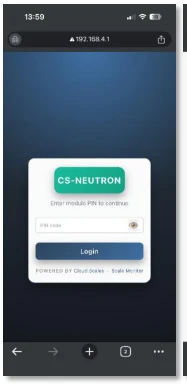
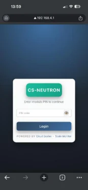
Once connected, open a web browser and go to:
https://192.168.4.1 or https://device-name.local
By default, device name is MID.
The login page will appear.
Enter your PIN and click Login.
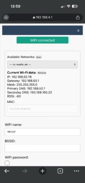
Step 4: Configure Wi-Fi Settings
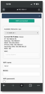
To connect Neutron to your main Wi-Fi network:
- Open the Wi-Fi page from the menu. • Enter the Wi-Fi name (SSID) and password (if required). • Click Save and wait for confirmation. • Click Reboot to apply the new settings.
After rebooting, Neutron will attempt to connect to the configured Wi-Fi network.
If the connection fails, repeat the steps above to verify and adjust the settings.
8.3. SCAN FOR AVAILABLE WI-FI NETWORKS
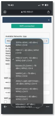
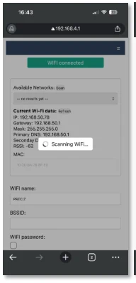
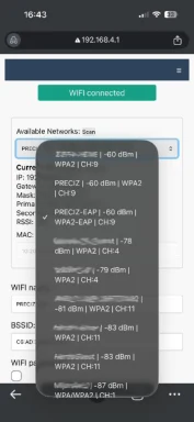
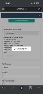
If you are unsure of the exact Wi-Fi name or want to see available nearby networs:
- Click Scan to search for nearby networks. • Select a Wi-Fi network from the list.
If Neutron is searching for a Wi-Fi network to connect to (Wi-Fi is selected as the communication interface and the module is not yet connected), scanning for available Wi- Fi networks is not possible at the same time.
When you selected network from the list, the BSSID field will be auto-filled. See BSSID chapter below for explanation when to use it and when not.
Signal strength is displayed in dBm (decibel-milliwatts). A higher value (closer to 0) means a stronger signal. Example: -40 dBm is better than -70 dBm.
Use the table below as a reference:
View original page 20 — diagrams and layout
| RSSI (dBm) Signal | Quality Description |
|---|---|
| -30 to -50 | Excellent Very strong and stable signal |
| -50 to -60 | Very Good Reliable connection |
| -60 to -70 | Good Normal operation expected |
| -70 to -80 | Weak Possible drops or interruptions |
| -80 to -90 | Very Weak Likely unstable connection |
| < -90 | Unusable Communication not reliable |
8.4. STANDARD WI-FI NETWORKS (OPEN / WPA2-PSK / WPA3-PSK)
Standard Wi-Fi networks use pre-shared key (PSK) or open authentication and are commonly found in home, small office, and standalone installations. These networks do not require a RADIUS server and are simpler to configure than Enterprise networks.
Neutron supports Open, WPA2-PSK, and WPA3-PSK security modes.
To connect Neutron to a Wi-Fi network, configure the following parameters as needed:
1. Open Networks (no security)
For an open (unencrypted) Wi-Fi network:
- Enter the Wi-Fi name (SSID) • Set Encryption to None
Warning: Open networks provide no security and allow unencrypted data transmission. Their use is not recommended except for testing or isolated environments.
2. Secured Networks (WPA2-PSK / WPA3-PSK)
For password-protected networks:
- Enter the SSID • Enter the Password • Set Encryption to WPA2/WPA3
8.5. STATIC IP CONFIGURATION
If the Wi-Fi network does not provide DHCP or if you prefer a fixed IP:
- Enter IP Address • Enter Subnet Mask • (Optional) Enter Gateway • (Optional) Enter Primary and Secondary DNS
View original page 21 — diagrams and layout
8.6. ENTERPRISE NETWORKS (WPA2/WPA3-ENTERPRISE)
Enterprise Wi-Fi networks use 802.1X authentication with a RADIUS server to provide centralized access control, improved security, and per-user or per-device authentication. Neutron supports the two most commonly used Enterprise EAP methods: EAP-TTLS and EAP-TLS.
Important: If the CA certificate is not configured, Neutron cannot validate the identity of the access point during the connection process (WIFI connection will be established also without CA certificate). This disables server authentication and may expose the connection to man-in-the-middle attacks. For security reasons, we strongly recommend always configuring a CA certificate, especially in production environments.
8.6.1. WPA2/WPA3-ENTERPRISE (EAP-TTLS)
EAP-TTLS is typically used in corporate networks where authentication is performed using a username and password, protected inside a secure TLS tunnel.
To connect Neutron to a WPA2/WPA3-Enterprise network using EAP-TTLS, configure the following:
- Enter the SSID • Set Encryption to WPA2/WPA3-Enterprise (EAP-TTLS) • Enter the Identity (outer identity, if required by the network) • Select a CA Certificate to allow Neutron to validate the access point • Enter the Username • Enter the Key / Password
Note: A CA certificate is strongly recommended to ensure secure server authentication and to prevent man-in- the-middle attacks.
8.6.2. WPA2/WPA3-ENTERPRISE (EAP-TLS)
EAP-TLS provides the highest level of security and is commonly used in managed corporate or industrial environments. Authentication is based on mutual certificate verification, eliminating the need for usernames and passwords.
To connect Neutron to a WPA2/WPA3-Enterprise network using EAP-TLS, configure the following:
- Enter the SSID • Set Encryption to WPA2/WPA3-Enterprise (EAP-TLS) • Enter the Identity (certificate identity or device identity) • Select a CA Certificate to validate the access point • Select the Client Certificate • Select the Client Private Key
Note: EAP-TLS requires a properly configured Public Key Infrastructure (PKI) and is recommended for production environments where strong device authentication is required.
View original page 22 — diagrams and layout
8.6.3. BSSID
You may enter the BSSID of the access point. The BSSID is the unique MAC address of a specific Wi-Fi access point. When BSSID is entered, Neutron will connect only to that exact access point.
This provides an additional layer of protection because the module will ignore any other access point broadcasting the same SSID.
This prevents accidental or malicious connection to another access point with the same network name.
If you do not know BSSID of the network scan for networks and select network you want to connect from the list and BSSID will be automatically filled out.
Important:
Do not use BSSID in environments where multiple access points share the same SSID (roaming networks).
If BSSID is set, Neutron will not roam and will connect only to the single access point with the specified MAC address, which may result in weak or lost connection if that access point becomes out of range.
8.7. COUNTRY OF USE
Available with firmware version 1.8.3 or later
Neutron requires the user to select the Country of use before operating the Wi-Fi interface.
The selected country determines the applicable Wi-Fi regulatory domain. This ensures that Neutron uses Wi-Fi channels and transmit-power limits appropriate for the country or region where the device is installed.
To configure the country of use:
1. Open the Wi-Fi settings page.
2. Select the country or region where the Neutron device will be installed and used.
3. Save the configuration.
4. Reboot the device if requested.
By default EU – Europe is set.
Important: Selecting the correct country of use is mandatory. Do not select another country or region merely to access different Wi-Fi channels or higher transmit-power settings. The device must always be configured for the country in which it is physically operated.
If Neutron is moved permanently to another country, update the Country of use setting before operating the Wi-Fi connection at the new location.
8.8. WIFI TRANSMIT (TX) POWER
Available with firmware version 1.8.3 or later
The WiFi TX power setting allows adjustment of the Wi-Fi transmitter output power.
Transmit power is shown in dBm .
View original page 23 — diagrams and layout
dBm means decibels referenced to 1 milliwatt. It is a logarithmic unit: increasing the value increases the transmitted Wi-Fi power.
| Setting | Approximate output power | Meaning | ||||||
|---|---|---|---|---|---|---|---|---|
| 20 dBm | 100 mW | Maximum selectable transmit power | ||||||
| 18 dBm | 63 mW | High transmit power | ||||||
| 15 dBm | 32 mW | Medium-high transmit power | ||||||
| 13 dBm | 20 mW | Medium transmit power | ||||||
| 11 dBm | 13 mW | Reduced transmit power | ||||||
| 8.5 dBm | 7 mW | Low transmit power | ||||||
| 7 dBm | 5 mW | Low transmit power | ||||||
| 5 dBm | 3 mW | Very low transmit power | ||||||
| 2 dBm | 1.6 mW | Minimum selectable transmit power |
The Auto setting allows Neutron to use the transmit-power setting determined automatically by the firmware and the selected country or regulatory domain.
Recommended setting
Use Auto unless there is a specific installation requirement.
Higher transmit power can improve communication range and signal reliability where the access point is distant or where moderate obstructions are present. However, higher transmit power may also increase radio interference, power consumption and unnecessary RF coverage outside the intended installation area.
Lower transmit power is recommended where:
- Neutron is installed close to the Wi-Fi access point.
- Multiple Neutron devices operate in the same area.
- Reduced RF emissions are required.
- The installation requires a limited Wi-Fi coverage area.
- Power consumption should be minimized.
Important: The highest selectable setting is 20 dBm and the lowest selectable setting is 2 dBm . The actual permitted output power may be limited by the selected country of use, Wi-Fi channel and applicable local radio regulations. Always configure the correct Country of use before selecting or changing Wi-Fi transmit power.
View original page 24 — diagrams and layout
9. ETHERNET SETTINGS
Under ethernet setting you can setup DHCP or static IP:
- Enter IP Address • Enter Subnet Mask • (Optional) Enter Gateway • (Optional) Enter Primary and Secondary DNS
Important:
Please note that Neutron requires additional addon (product code: CS-NA-ETH). If Ethernet addon is not present or not working you will not be able to see menu to configure Ethernet settings.
View original page 25 — diagrams and layout
10. SERIAL CONNECTION
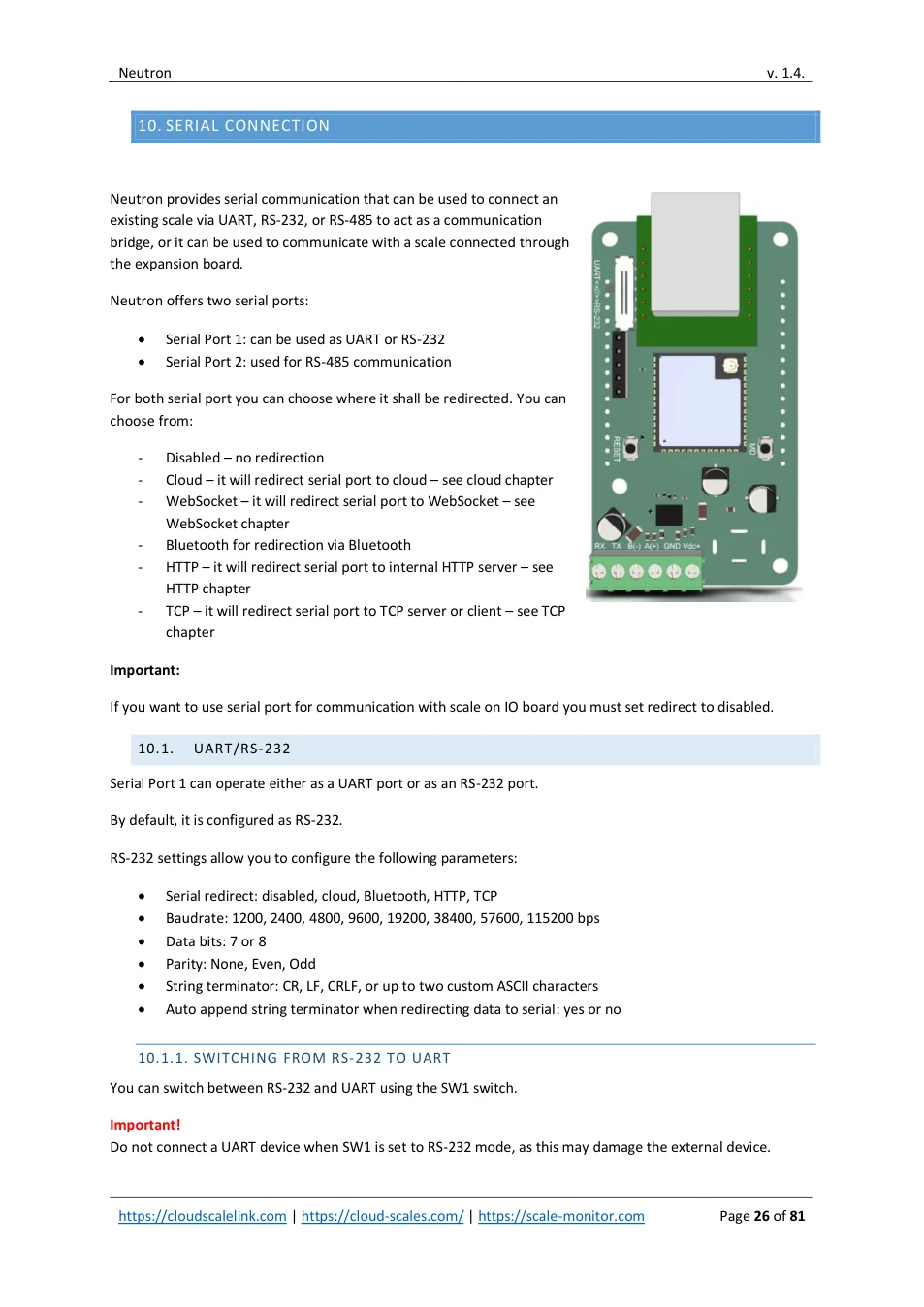
Neutron provides serial communication that can be used to connect an existing scale via UART, RS-232, or RS-485 to act as a communication bridge, or it can be used to communicate with a scale connected through the expansion board.
Neutron offers two serial ports:
- Serial Port 1: can be used as UART or RS-232 • Serial Port 2: used for RS-485 communication
For both serial port you can choose where it shall be redirected. You can choose from:
- Disabled – no redirection - Cloud – it will redirect serial port to cloud – see cloud chapter - WebSocket – it will redirect serial port to WebSocket – see WebSocket chapter - Bluetooth for redirection via Bluetooth - HTTP – it will redirect serial port to internal HTTP server – see HTTP chapter - TCP – it will redirect serial port to TCP server or client – see TCP chapter
Important:
If you want to use serial port for communication with scale on IO board you must set redirect to disabled.
10.1. UART/RS-232
Serial Port 1 can operate either as a UART port or as an RS-232 port.
By default, it is configured as RS-232.
RS-232 settings allow you to configure the following parameters:
- Serial redirect: disabled, cloud, Bluetooth, HTTP, TCP • Baudrate: 1200, 2400, 4800, 9600, 19200, 38400, 57600, 115200 bps • Data bits: 7 or 8 • Parity: None, Even, Odd • String terminator: CR, LF, CRLF, or up to two custom ASCII characters • Auto append string terminator when redirecting data to serial: yes or no
10.1.1. SWITCHING FROM RS-232 TO UART
You can switch between RS-232 and UART using the SW1 switch.
Important! Do not connect a UART device when SW1 is set to RS-232 mode, as this may damage the external device.
View original page 26 — diagrams and layout
Likewise, do not connect an external RS-232 device to Neutron when SW1 is set to UART mode as this will damage Neutron.
Always turn off Neutron before switching SW1 between RS-232 and UART to prevent hardware damage.
10.1.2. UART/RS-232 WIRE DIAGRAM USING TERMINAL BLOCK
To connect an RS-232 or UART device, use the terminal block as follows:
- RX: connect this pin to the transmit line (TX) of the external device • TX: connect this pin to the receive line (RX) of the external device • GND: connect to the ground of the external device
Correct wiring of TX, RX, and GND is required for proper communication.
10.2. RS-485
Serial Port 2 is dedicated for RS-485 communication.
RS-485 supports a multi-drop connection, where multiple client devices can be connected on the same pair of wires and communicate with a single master device. This allows several scales or peripherals to share one communication line.
RS-485 port is also used to connect devices that communicate over long distances (up 1200 meters) or in electrically noisy environments, where differential signalling provides improved reliability.
RS-485 settings allow you to configure the following parameters:
- Serial redirect: disabled, cloud, Bluetooth, HTTP, TCP • RS-485 address: 0-255 • Baudrate: 1200, 2400, 4800, 9600, 19200, 38400, 57600, 115200 bps • Data bits: 7 or 8 • Parity: None, Even, Odd • String terminator: CR, LF, CRLF, or up to two custom ASCII characters • Auto append string terminator when redirecting data to serial: yes or no
Neutron automatically manages the RS-485 driver control, ensuring proper switching between transmit and receive modes during communication.
10.2.1. RS-485 WIRING
To connect an RS-485 device, use the terminal block as follows:
- A + : connect this pin to the A + line on the external device or RS-485 bus • B - : connect this pin to the B - line on the external device or RS-485 bus
10.3. MODBUS RTU
Available with firmware version 1.8 or later
Neutron supports Modbus RTU communication through the RS-232 or RS-485 serial interface. Modbus RTU can be used for communication with PLCs, SCADA systems, HMI panels, industrial PCs and other Modbus master devices.
View original page 27 — diagrams and layout
To use Modbus RTU, select the appropriate serial interface under Scale communication interface :
- RS-232 for Modbus RTU communication through the UART / RS-232 port.
- RS-485 for Modbus RTU communication through the RS-485 port.
The serial communication parameters configured in Neutron must match the settings of the Modbus master:
- Baud rate
- Data bits
- Parity
- Stop bits
- Modbus slave address / Unit ID
The Modbus slave address is configured using parameter MBA . The default address is 1 .
RS-232 connection
For RS-232 communication, connect:
- Neutron TX to master device RX
- Neutron RX to master device TX
- Neutron GND to master device signal ground
TX and RX may need to be crossed depending on whether the connected devices are configured as DTE or DCE.
RS-485 connection
For RS-485 communication, connect:
- Neutron A(+) to the master or bus A
- Neutron B(-) to the master or bus B
- Signal GND, where required by the installation
Use a daisy-chain bus topology for RS-485 installations. Do not use star wiring. Where required, install line termination only at the two physical ends of the RS-485 bus.
Important: RS-485 terminal naming is not fully standardized between manufacturers. If communication is not established, verify the A/B polarity, serial parameters and Modbus slave address.
For the complete register map, command list, data format and calibration interface, refer to the separate document:
CloudScale Neutron Modbus User Manual : https://apps.scale-monitor.com/files/Neutron/CS-NEUTRON_EN_Modbus_latest.pdf
View original page 28 — diagrams and layout
11. CLOUD (MQTT)
Under Cloud Settings you must configure the parameters that Neutron will use to establish a connection with the MQTT broker.
The following parameters are available:
Enabled
If Cloud is set to “Disabled,” Neutron will not connect to the cloud, and remote management will not be available. If enabled Neutron will try to establish connection with cloud.
Connection Type
Select the appropriate connection type based on your network environment and security requirements:
- MQTT Unsecured, unencrypted communication via TCP. Use only in trusted local networks or in environments where transmitted data is not sensitive or confidential. • WSS (Secure WebSocket) Encrypted WebSocket communication using TLS. Recommended for secure, real-time data exchange over public or untrusted networks. • MQTTS – Username & Password Secure MQTT communication using TLS encryption with username and password authentication . If you are not connecting to the Scale Monitor Cloud, set Credentials to Custom and enter the username and password that Neutron will use to authenticate with your MQTT broker. • MQTTS – Client Certificate (mTLS) Secure MQTT communication using TLS encryption with mutual authentication (client certificate) . When using mTLS:
o
Set Credentials to None
o
Authentication is performed exclusively using the client certificate and private key
Important Note
When connecting to an MQTT broker using secured communication (WSS or MQTTS) , and the broker uses a self-signed certificate or a certificate issued by a non-trusted Certificate Authority , you must provide a CA certificate.
Without a valid CA certificate, Neutron cannot verify the broker identity , and the connection will fail.
For production environments, always use trusted certificates and encrypted connections to ensure data integrity and security.
Server: enter the server URL or IP address.
Port: enter the port number used by the server for incoming connections.
Client ID: by default client id is module ID but you may change it according to you needs.
Credentials:
- Built-in – used for connection to Scale Monitor cloud • Custom – you provide your own username and password
View original page 29 — diagrams and layout
- None - username and password are not used for authentication (use this when connecting to MQTT broker that does not require authentication or when using MQTTS with client certificate).
QoS: Quality of Service.
This defines how messages are delivered between Neutron and the cloud:
- QoS 0: the fastest method; messages are delivered once without confirmation. This is default value. • QoS 1: guaranteed delivery; the message is delivered at least once and confirmed by the server. • QoS 2: the highest reliability level; messages are delivered exactly once using a two-phase handshake. This prevents duplicates and ensures perfect accuracy, but requires more processing and bandwidth.
Higher QoS increases reliability but use more bandwidth and therefore also some delay between packages will occur. If you have reliable internet connection QoS you can use QoS 0 but, if your connection is not reliable you shall use QoS 1. QoS 2 is not recommended for continuous communications and shall be used only special cases.
Group topic: for manufacturer use only.
Group topic without SN/MID: for manufacturer use only.
11.1. TOPICS
Neutron uses predefined MQTT topics that are always divided into RX (Receive) and TX (Transmit) topics.
- RX topics are used to receive commands . Neutron automatically subscribes to all RX topics. • TX topics are used to publish responses or data . Neutron does not subscribe to TX topics.
All topics start with the prefix $CSL, followed by the Module ID (MID) .
| Topic | Meaning |
|---|---|
| $CSL/MID/RX | Command input topic for UART / RS-232 communication. Neutron subscribes to this topic. Commands received here are forwarded to UART/RS-232. The module never publishes data on this topic. |
| $CSL/ MID/TX | Output topic for UART / RS-232 data. Neutron publishes data received from RS-232 on this topic. The module does not subscribe to this topic. |
| $CSL/MID/RX/S1 | Command input topic for RS-485 communication. Neutron subscribes to this topic. Commands received here are forwarded to RS-485. The module never publishes data on this topic. |
| $CSL/ MID/TX/S1 | Output topic for RS-485 data. Neutron publishes data received from RS-485 on this topic. The module does not subscribe to this topic. |
View original page 30 — diagrams and layout
| $CSL/MID/RX/SC | Command input topic scale communication. Neutron subscribes to this topic. Commands received here are forwarded to scale. The module never publishes data on this topic. |
|---|---|
| $CSL/MID/TX/SC | Output topic for scale data. Neutron publishes data received from scale on this topic. The module does not subscribe to this topic. |
| $CSL/MID/RX/IO | Command input topic for digital I/O control, such as reading digital input states or setting digital output states. Neutron subscribes to this topic. The module never publishes data on this topic. |
| $CSL/MID/TX/IO | Output topic for digital I/O responses. Neutron publishes responses to I/O commands on this topic. The module does not subscribe to this topic. |
| $CSL/MID/STATUS | Status topic used to report module connection state. Neutron publishes a Connected message when online. The broker publishes a Disconnected message using the Last Will mechanism. Status message has following form: • Connected message: STA;S=C;MID=XXXXXX • Disconnected message: STA;S=D;MID=XXXXXX |
| $CSL/MID/DEBUG | On this topic messages for debugging communication will be published. Note: if you want to debug WIFI communication you must use Bluetooth debugging. See chapter 13.1. |
11.2. FREE ONLINE DEBUG TOOL FOR MQTT
You can use our free online debugging tool available on https://apps.scale-monitor.com and click on MQTT client.
View original page 31 — diagrams and layout
11.3. AMAZON WEB SERVICES – AWS IOT CLOUD
Amazon Web Services (AWS) is a secure and scalable cloud platform that provides managed infrastructure for IoT deployments, including device connectivity, authentication, and message routing through AWS IoT Core . It enables reliable, encrypted communication between devices and cloud applications using industry-standard protocols such as MQTT over TLS.
Neutron integrates seamlessly with AWS IoT Core, allowing it to securely publish data and receive commands using predefined MQTT topics. Neutron supports both certificate-based authentication (mTLS) and encrypted communication, ensuring secure device identity verification and data integrity. This integration enables remote device management, real-time data exchange, and scalable deployment of Neutron modules in cloud-based environments.
11.3.1. CREATE NEW THING IN AWS IOT CORE
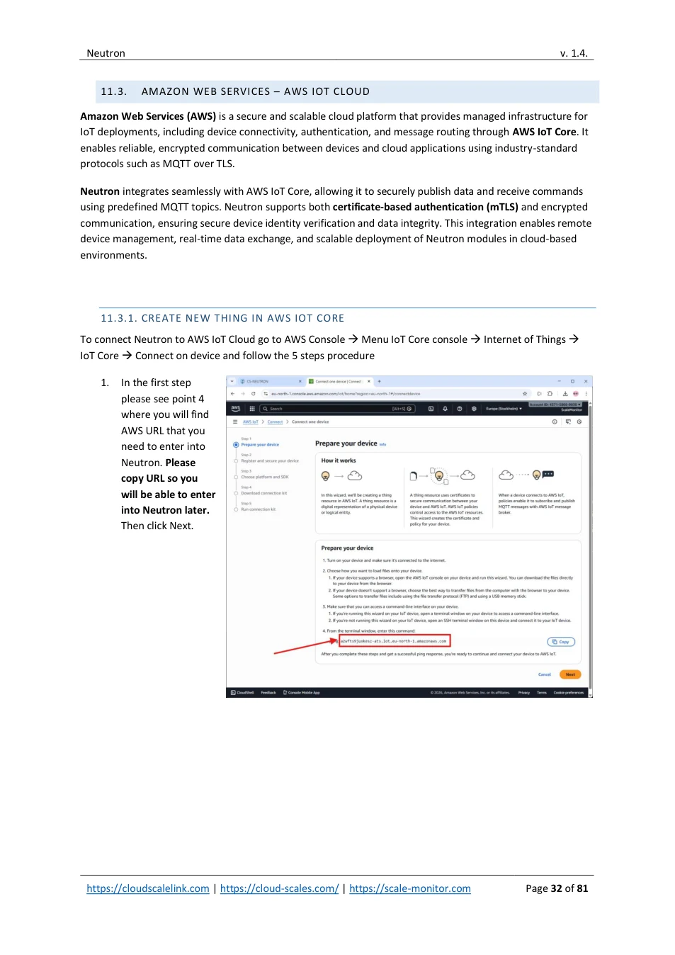
To connect Neutron to AWS IoT Cloud go to AWS Console → Menu IoT Core console → Internet of Things → IoT Core → Connect on device and follow the 5 steps procedure
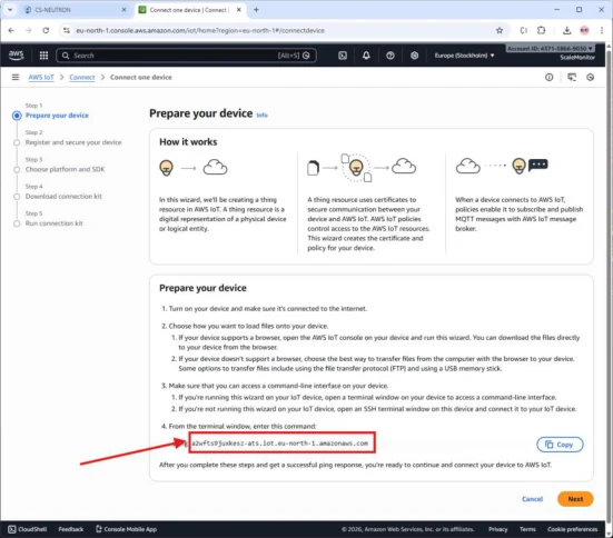
1. In the first step please see point 4 where you will find AWS URL that you need to enter into Neutron. Please copy URL so you will be able to enter into Neutron later. Then click Next.
View original page 32 — diagrams and layout
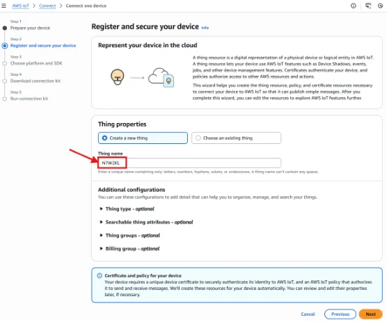
2. In the second step select “Create a new thing” and into Thing name field enter Neutron MID.
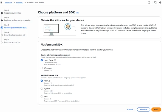
3. In the third step you can choose either Linux/macOS or Windows for device platform and AWS IoT Device SDK choose Node.js and click Next.
View original page 33 — diagrams and layout
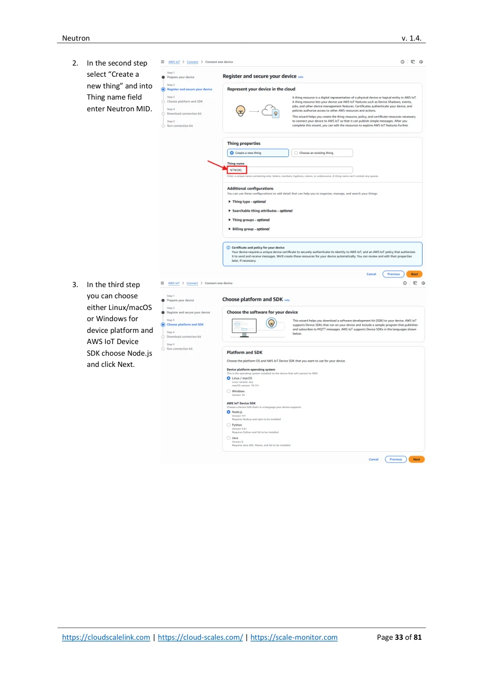
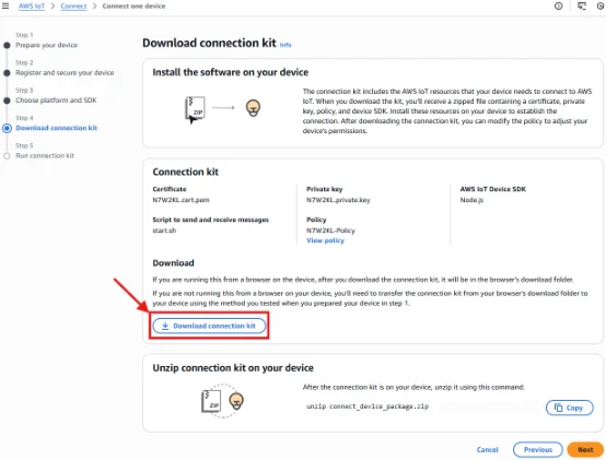
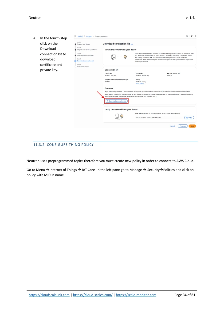
4. In the fourth step click on the Download connection kit to download certificate and private key.
11.3.2. CONFIGURE THING POLICY
Neutron uses preprogrammed topics therefore you must create new policy in order to connect to AWS Cloud.
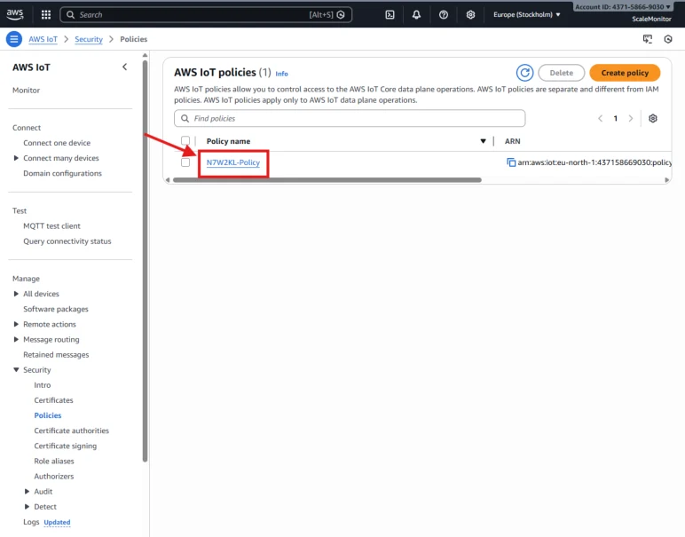
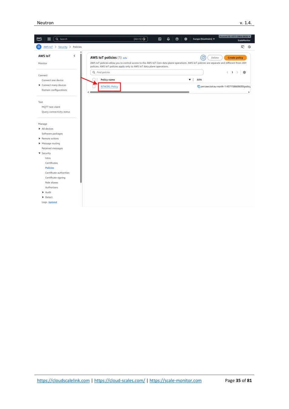
Go to Menu → Internet of Things → IoT Core in the left pane go to Manage → Security → Policies and click on policy with MID in name.
View original page 34 — diagrams and layout
View original page 35 — diagrams and layout
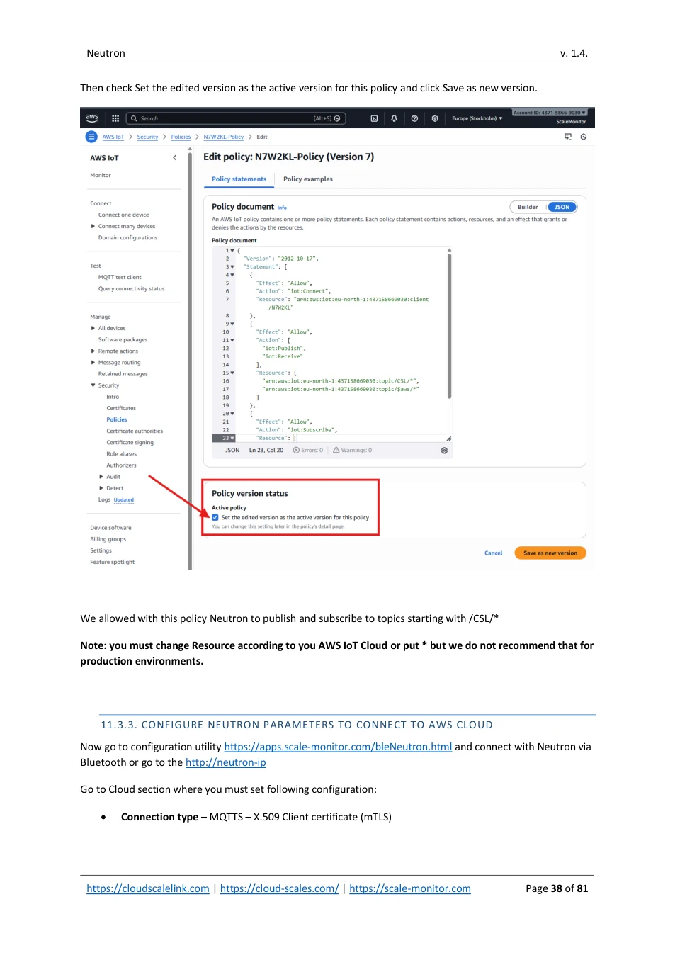
Click on Edit active version:
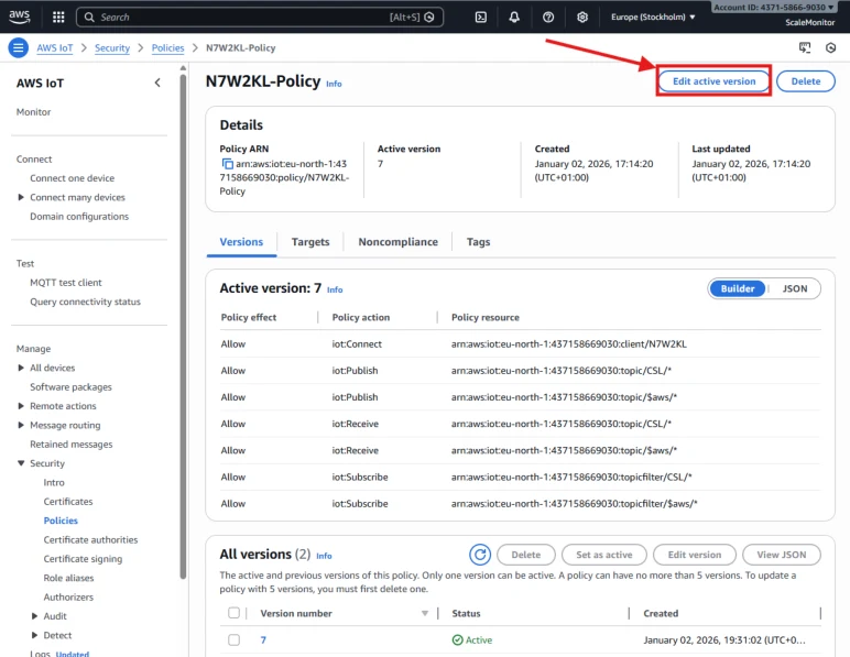
In the edit policy window click on JSON and paste JSON of edited policy in our example it is:
{
"Version": "2012-10-17",
"Statement": [
{
"Effect": "Allow",
"Action": "iot:Connect",
"Resource": "arn:aws:iot:eu-north-1:437158669030:client/N7W2KL"
},
{
"Effect": "Allow",
"Action": [
View original page 36 — diagrams and layout
"iot:Publish",
"iot:Receive"
],
"Resource": [
"arn:aws:iot:eu-north-1:437158669030:topic/CSL/*",
"arn:aws:iot:eu-north-1:437158669030:topic/$aws/*"
]
},
{
"Effect": "Allow",
"Action": "iot:Subscribe",
"Resource": [
"arn:aws:iot:eu-north-1:437158669030:topicfilter/CSL/*",
"arn:aws:iot:eu-north-1:437158669030:topicfilter/$aws/*"
]
}
]
}
View original page 37 — diagrams and layout
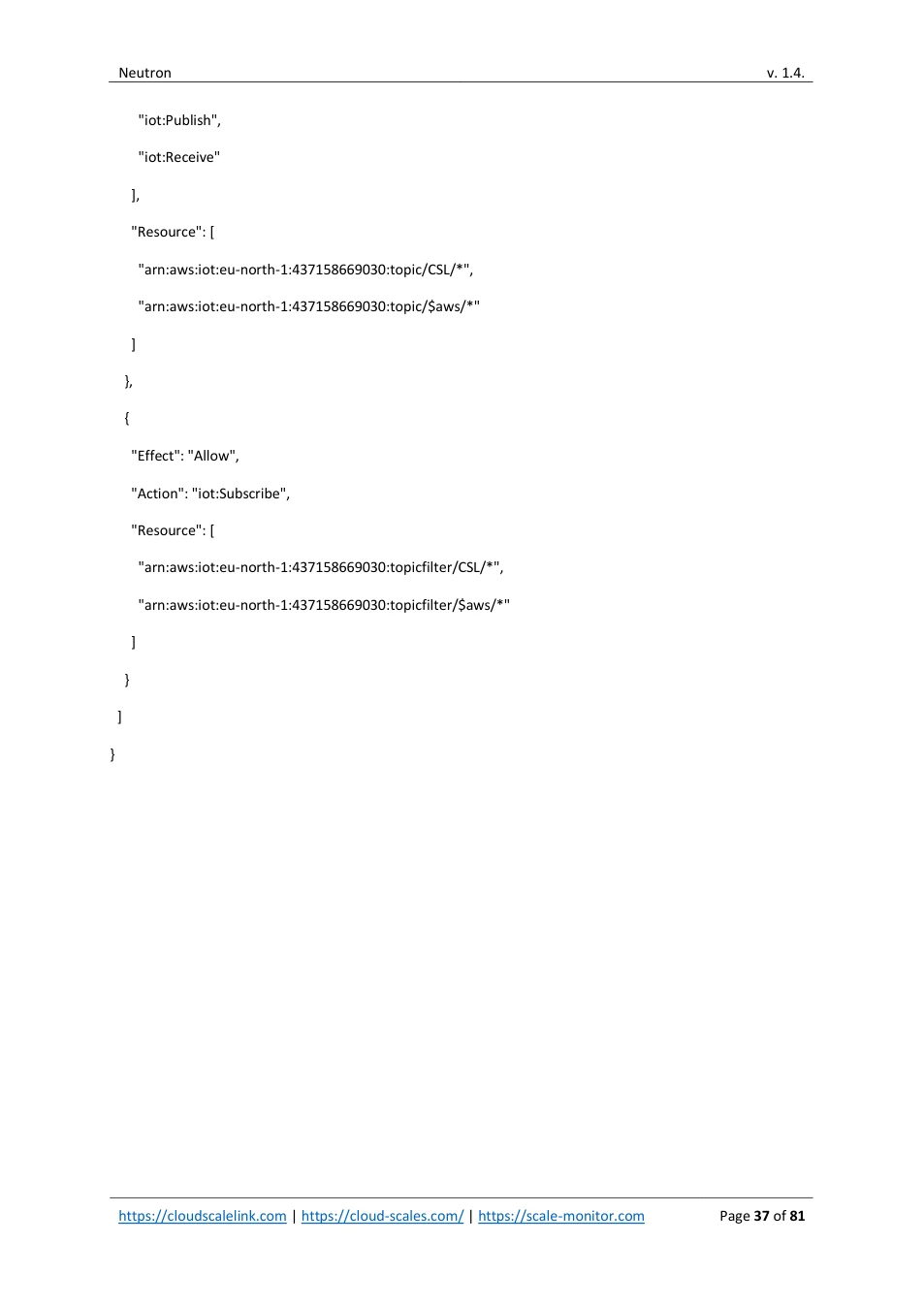
Then check Set the edited version as the active version for this policy and click Save as new version.
We allowed with this policy Neutron to publish and subscribe to topics starting with /CSL/*
Note: you must change Resource according to you AWS IoT Cloud or put * but we do not recommend that for production environments.
11.3.3. CONFIGURE NEUTRON PARAMETERS TO CONNECT TO AWS CLOUD
Now go to configuration utility https://apps.scale-monitor.com/bleNeutron.html and connect with Neutron via Bluetooth or go to the http://neutron-ip
Go to Cloud section where you must set following configuration:
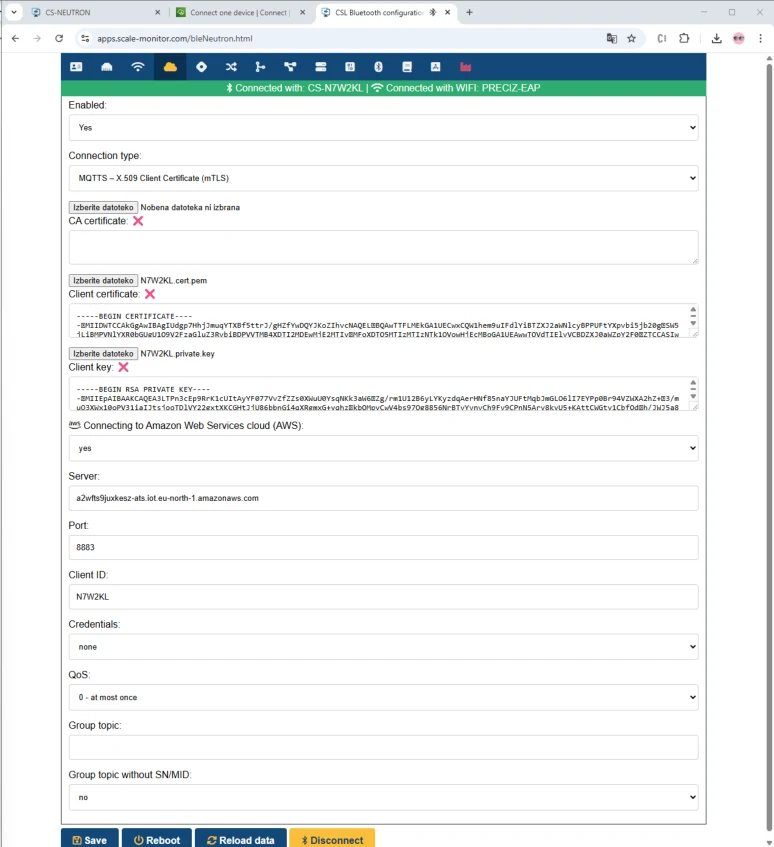
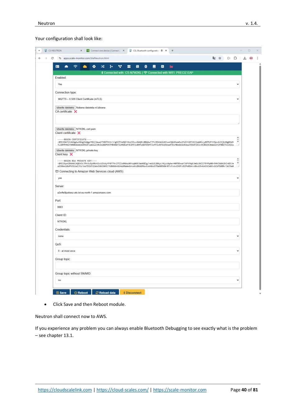
- Connection type – MQTTS – X.509 Client certificate (mTLS)
View original page 38 — diagrams and layout
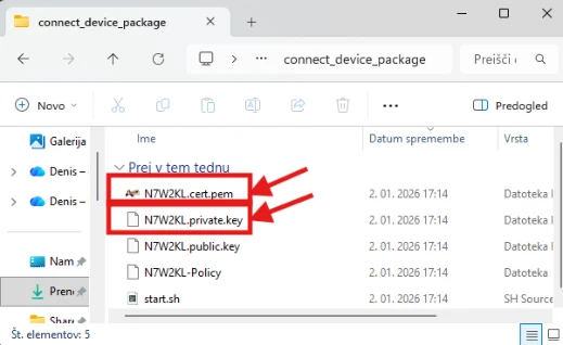
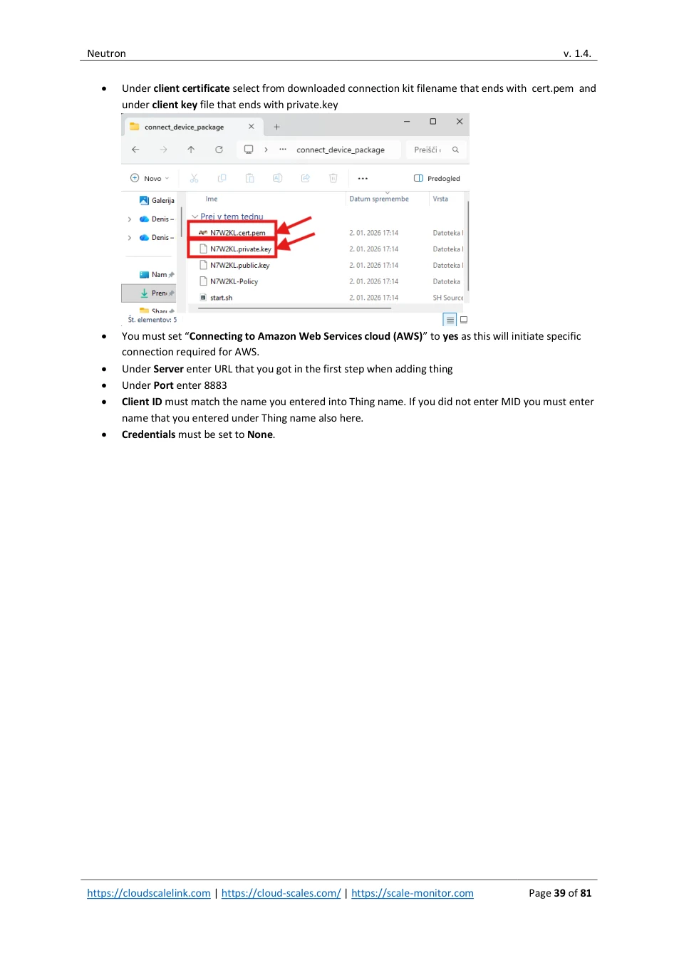
- Under client certificate select from downloaded connection kit filename that ends with cert.pem and under client key file that ends with private.key
- You must set “ Connecting to Amazon Web Services cloud (AWS) ” to yes as this will initiate specific connection required for AWS. • Under Server enter URL that you got in the first step when adding thing • Under Port enter 8883 • Client ID must match the name you entered into Thing name. If you did not enter MID you must enter name that you entered under Thing name also here. • Credentials must be set to None .
View original page 39 — diagrams and layout
Your configuration shall look like:
- Click Save and then Reboot module.
Neutron shall connect now to AWS.
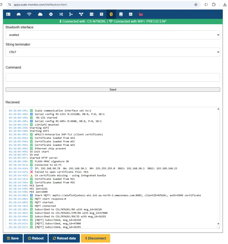
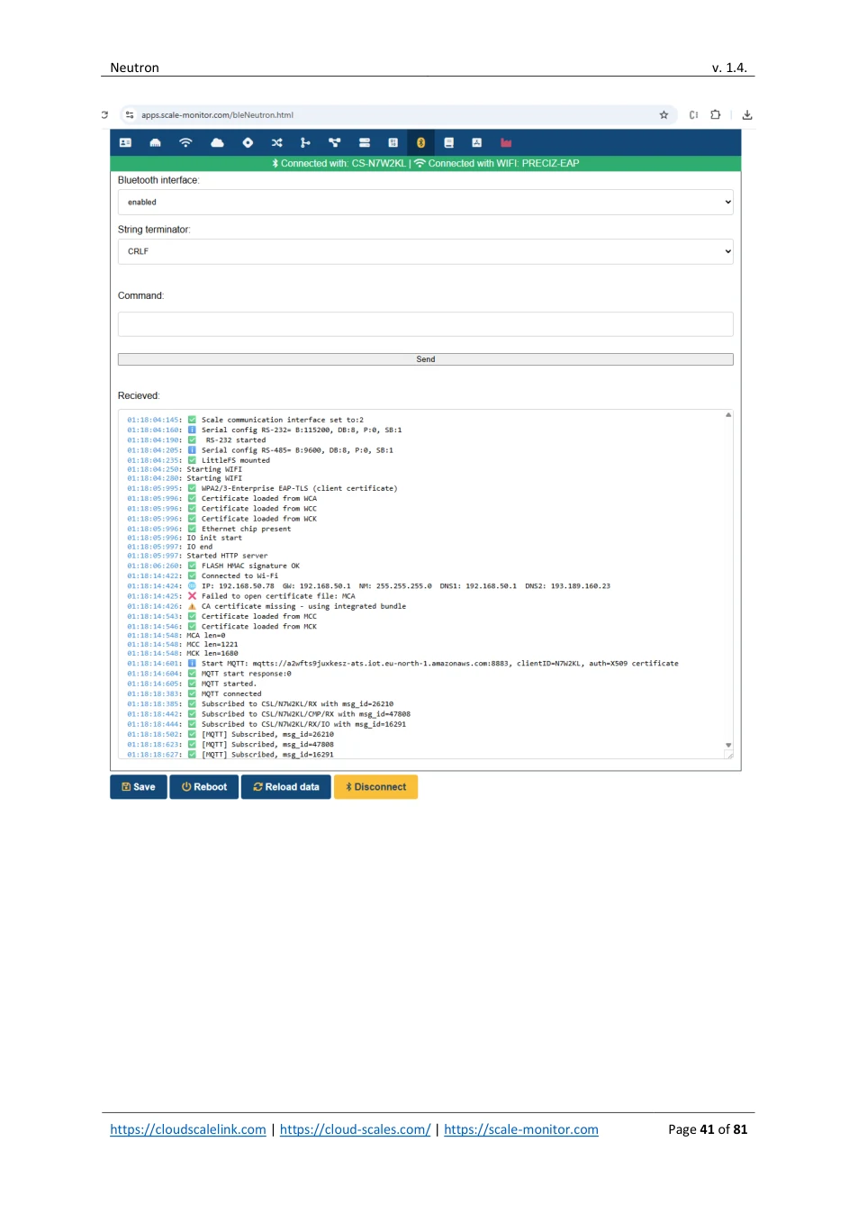
If you experience any problem you can always enable Bluetooth Debugging to see exactly what is the problem – see chapter 13.1.
View original page 40 — diagrams and layout
View original page 41 — diagrams and layout
11.3.4. TESTING NEUTRON CONNECTION WITH AWS IOT CLOUD
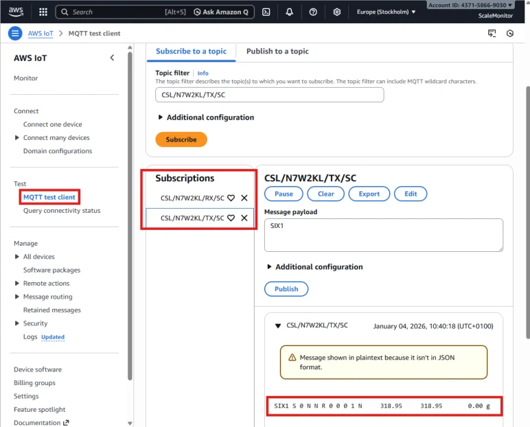
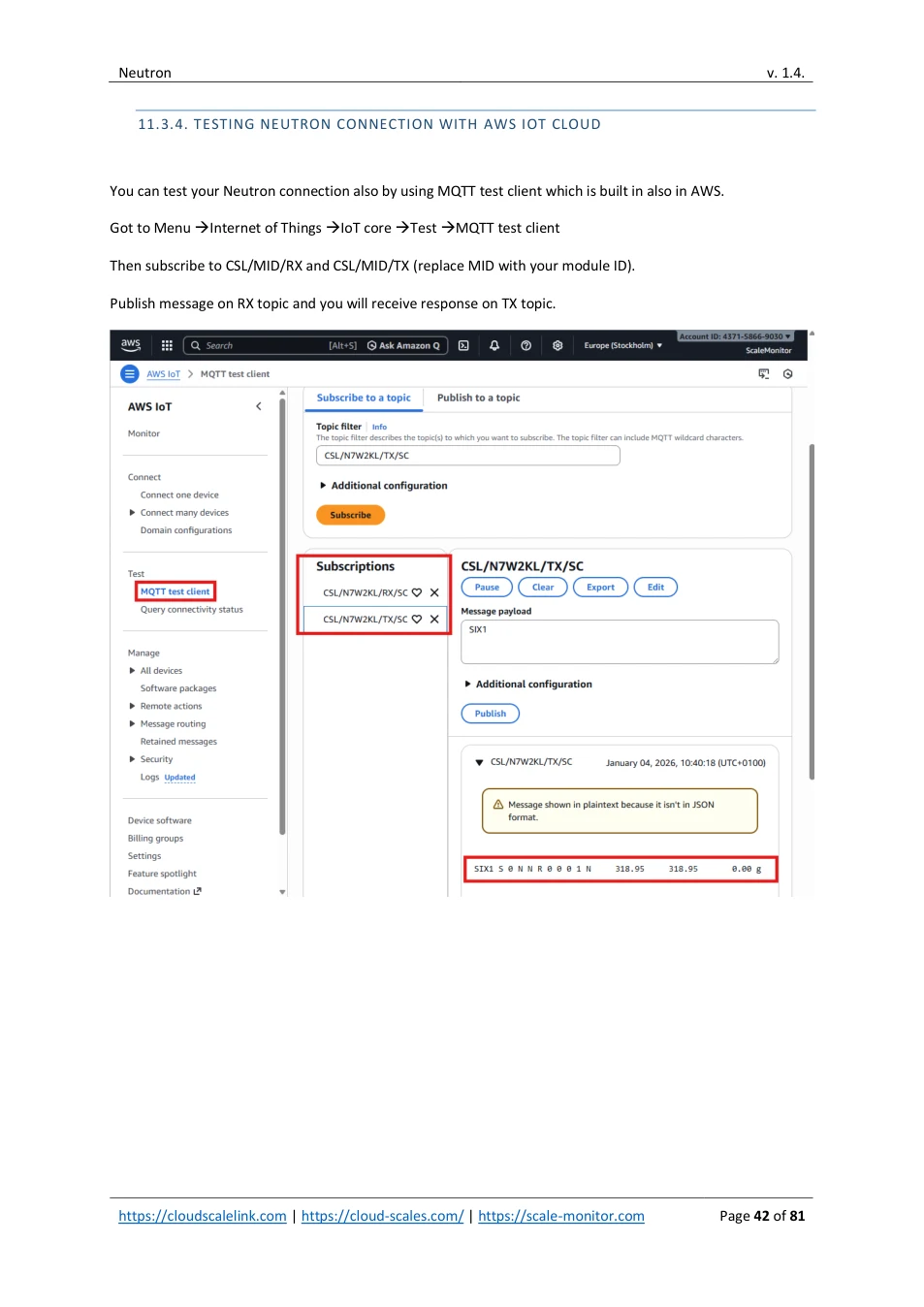
You can test your Neutron connection also by using MQTT test client which is built in also in AWS.
Got to Menu → Internet of Things → IoT core → Test → MQTT test client
Then subscribe to CSL/MID/RX and CSL/MID/TX (replace MID with your module ID).
Publish message on RX topic and you will receive response on TX topic.
View original page 42 — diagrams and layout
12. MICROSFT AZURE IOT CLOUD
Neutron supports connection to Azure IOT Cloud. Connection is established via MQTTS and by using SAS token.
Please note that since Azure does not support multiple topics you can use only one topic for communication. Therefore you can not use simultaneous RS-232 cloud redirection together with using scale or RS-485, IO etc..
You must set only one feature to bridge it cloud. If multiple bridges are set the first feature metting first condition will be hadled and others will be ignored. Priority is the following:
1. Scale 2. RS-232 3. RS-485
So if you set scale communication interface to cloud while also setting RS-232 bridge to cloud only scale will be handled. This is not limitation of Neutron but limitation of Azure which allows only single topic.
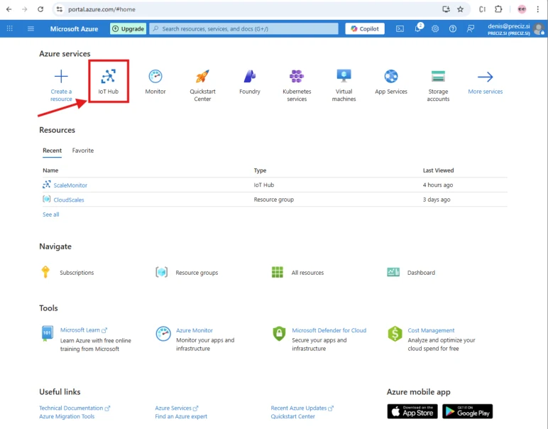
1. To connect Neutron to Azure please first login to Azure → IoT Hub
View original page 43 — diagrams and layout
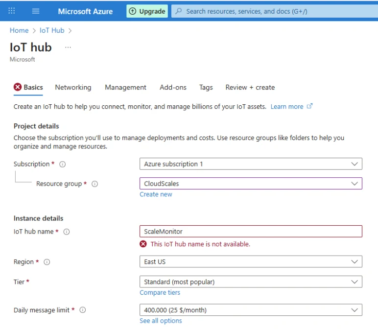
2. Create or choose IoT Hub
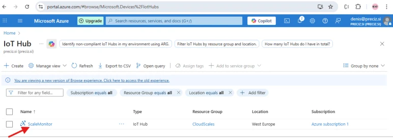
3. After IoT Hub is generated click on IT
View original page 44 — diagrams and layout
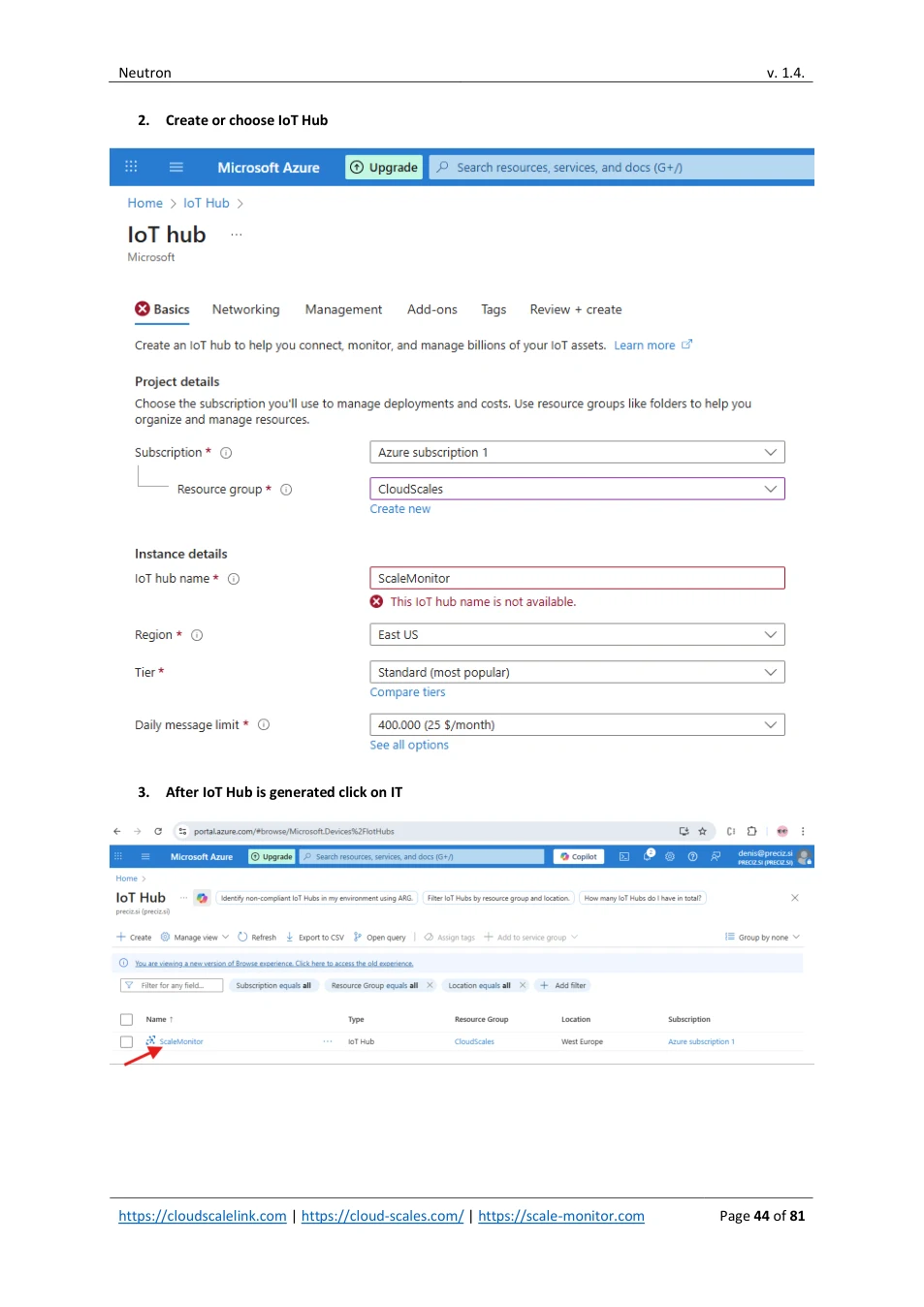
4. Click Devices
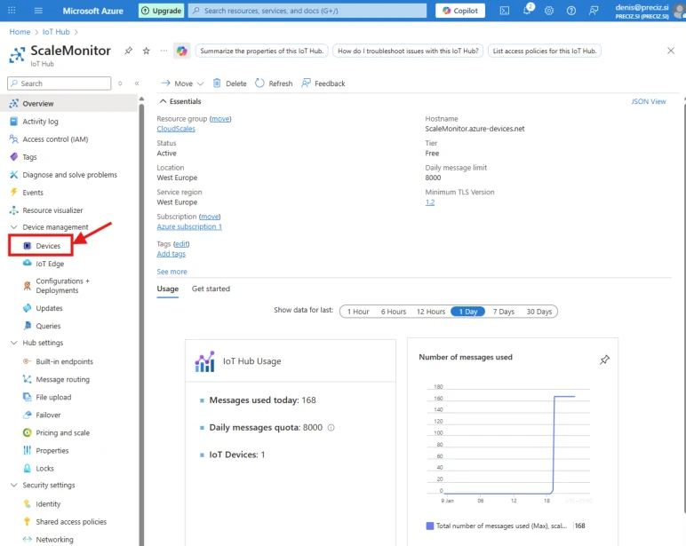
5. Click Add device and set: - Client ID: Please note that Client ID must be MID (module ID) or custom but in that case remember to change client ID also under Cloud settings on Neutron - Authentication type: symmetric key (you can use also X.509 if you want) - Auto-generate keys: yes - Connect this device to an IoT hub: enabled
View original page 45 — diagrams and layout
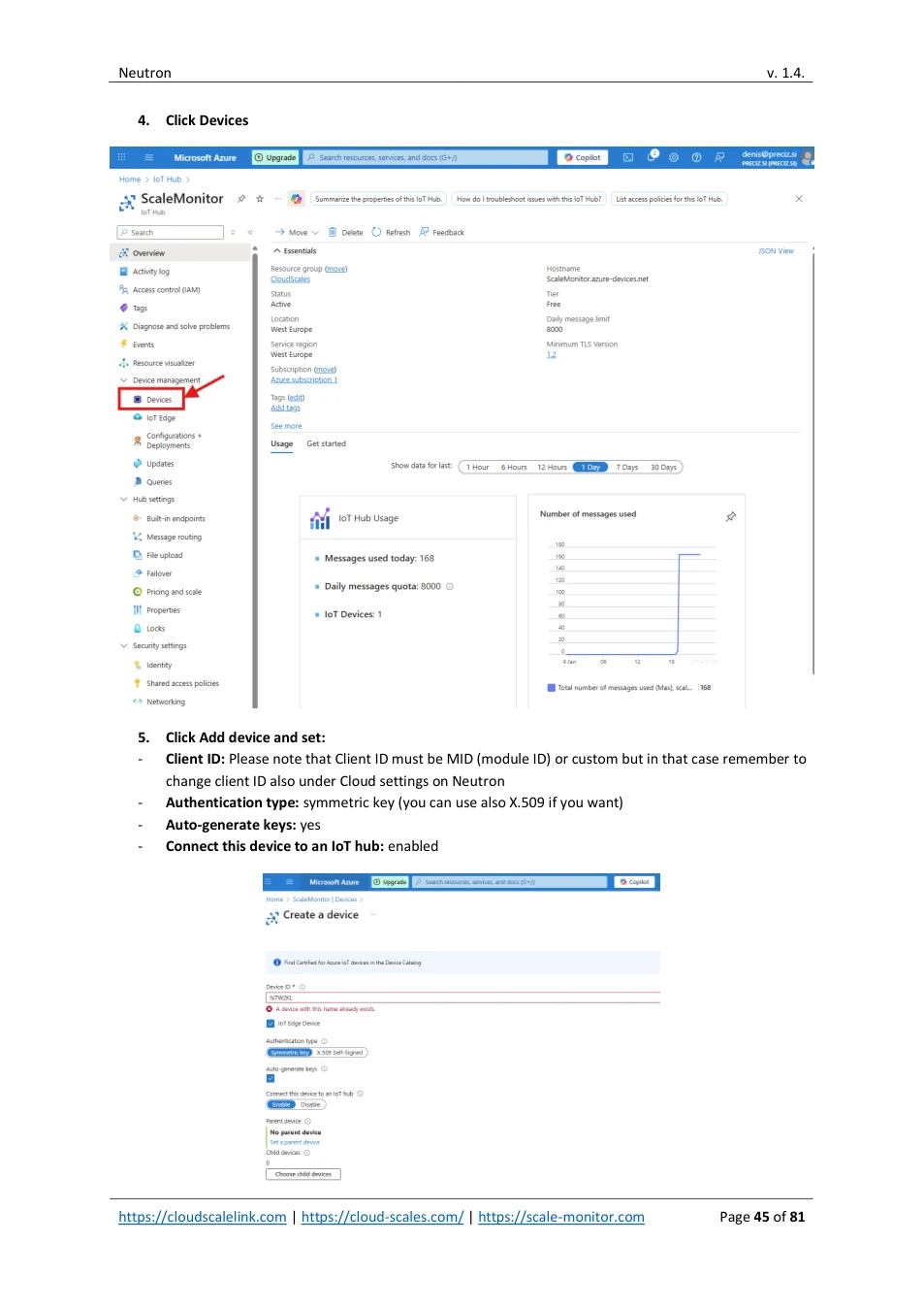
This will create new device.
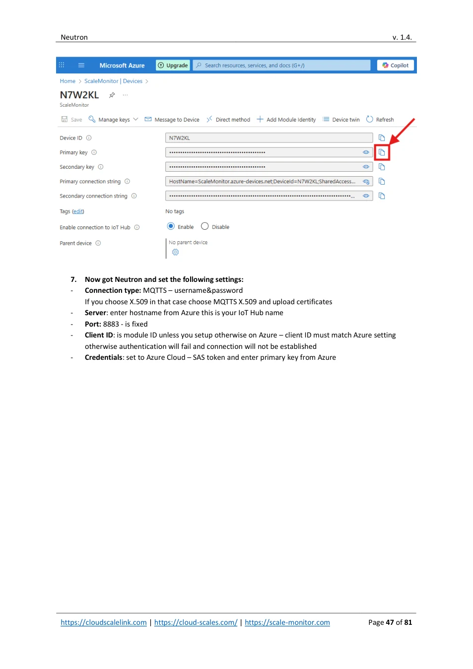
6. Once device is created click on the device and then click on primary connection string to retrieve the hostname
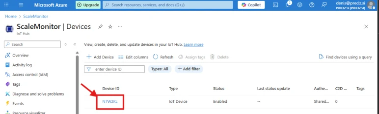
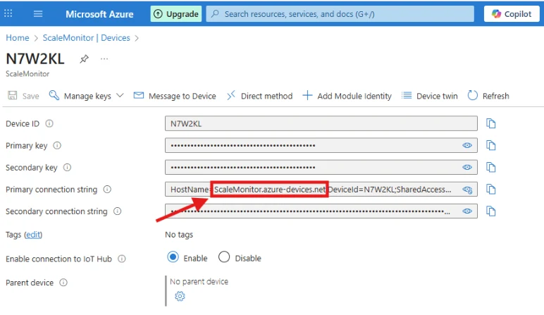
Hostname must be entered in Neutron under server.
Click on copy icon of primary key to copy primary key.
View original page 46 — diagrams and layout
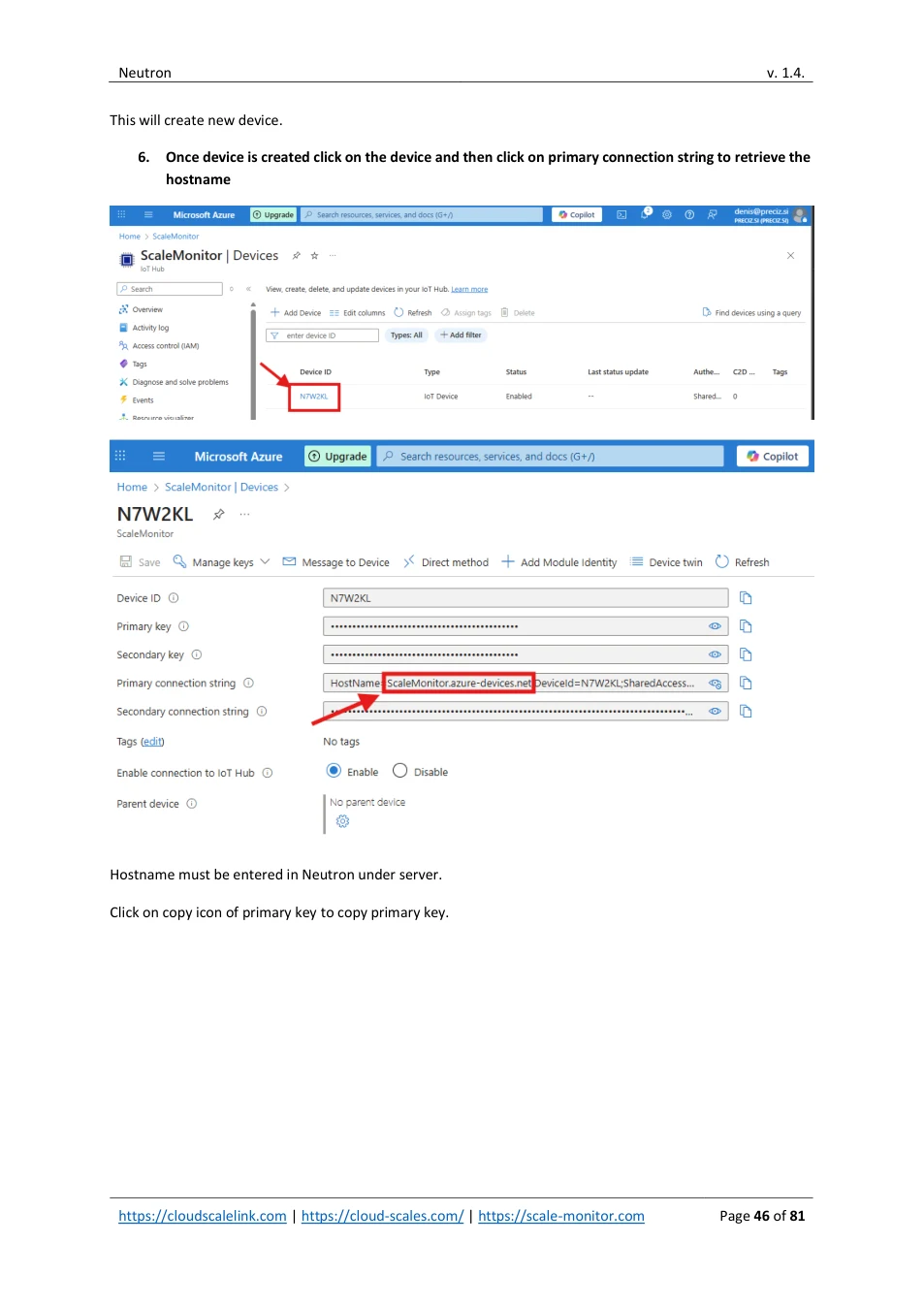
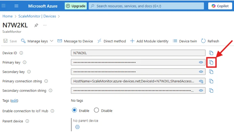
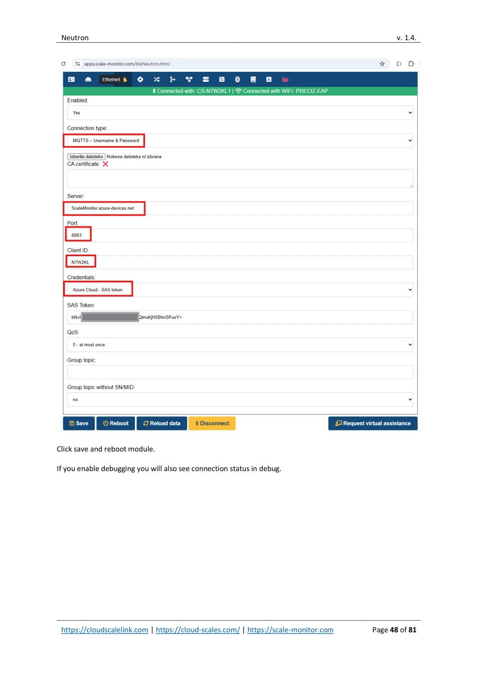
7. Now got Neutron and set the following settings: - Connection type: MQTTS – username&password If you choose X.509 in that case choose MQTTS X.509 and upload certificates - Server : enter hostname from Azure this is your IoT Hub name - Port: 8883 - is fixed - Client ID : is module ID unless you setup otherwise on Azure – client ID must match Azure setting otherwise authentication will fail and connection will not be established - Credentials : set to Azure Cloud – SAS token and enter primary key from Azure
View original page 47 — diagrams and layout
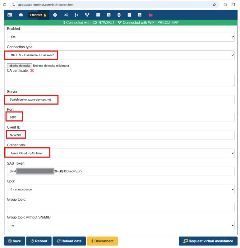
Click save and reboot module.
If you enable debugging you will also see connection status in debug.
View original page 48 — diagrams and layout
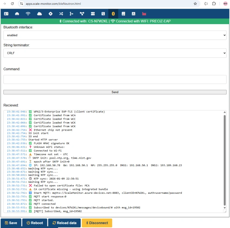
12.1. TEST AZURE COMMUNICATION
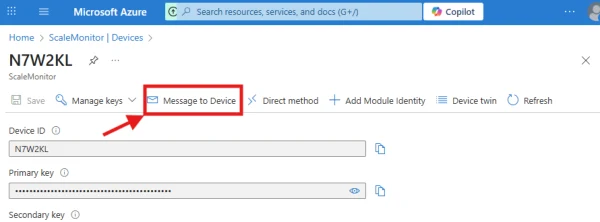
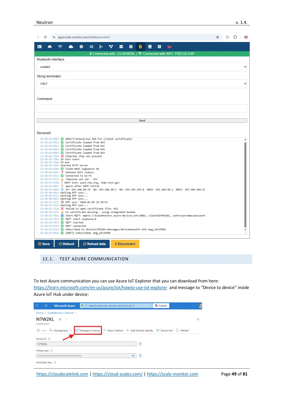
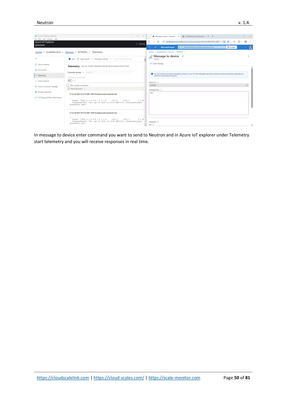
To test Azure communication you can use Azure IoT Explorer that you can download from here: https://learn.microsoft.com/en-us/azure/iot/howto-use-iot-explorer and message to “Device to device” inside Azure IoT Hub under device:
View original page 49 — diagrams and layout
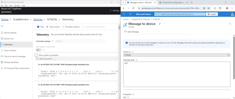
In message to device enter command you want to send to Neutron and in Azure IoT explorer under Telemetry start telemetry and you will receive responses in real time.
View original page 50 — diagrams and layout
13. WEBSOCKET
This section describes the WebSocket communication between the device and a remote server. WebSocket communication enables bidirectional, real-time data exchange.
WebSocket can be use for redirection of serial port (RS-232 or RS-485 – chose WebSocket under serial redirect) or for communication with scale (set scale communication interface to WebSocket).
Neutron supports both encrypted and unencrypted connections and additionally also HTTP Basic authentication.
13.1. WEBSOCKET QUICK CONFIGURATION
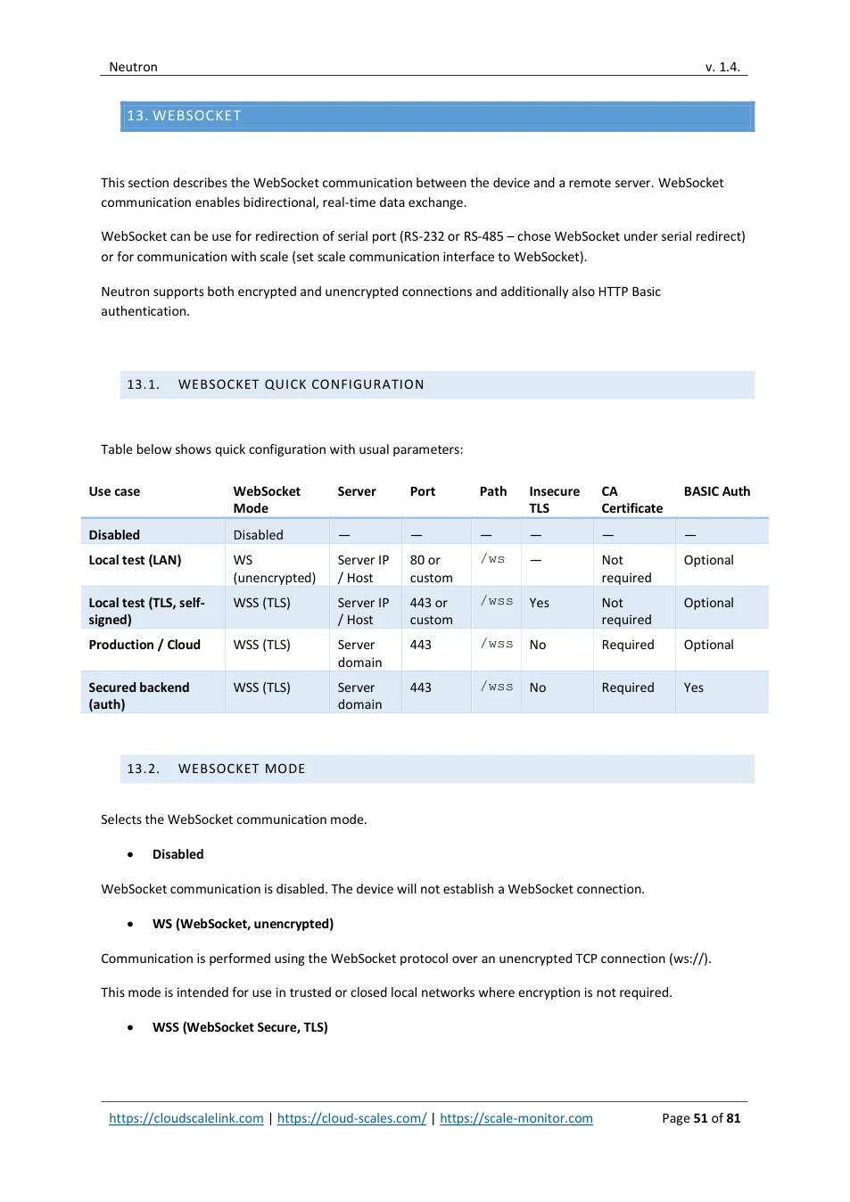
Table below shows quick configuration with usual parameters:
| Use case | WebSocket | Server | Port | Path | Insecure | CA | BASIC Auth | ||||||||||||||||
|---|---|---|---|---|---|---|---|---|---|---|---|---|---|---|---|---|---|---|---|---|---|---|---|
| Mode | TLS | Certificate | |||||||||||||||||||||
| Disabled | Disabled | — | — | — | — | — | — | ||||||||||||||||
| Local test (LAN) | WS (unencrypted) | Server IP / Host | 80 or custom | /ws | — | Not required | Optional | ||||||||||||||||
| Local test (TLS, self- | WSS (TLS) | Server IP | 443 or | /wss | Yes | Not | Optional | ||||||||||||||||
| signed) | / Host | custom | required | ||||||||||||||||||||
| Production / Cloud | WSS (TLS) | Server domain | 443 | /wss | No | Required | Optional | ||||||||||||||||
| Secured backend | WSS (TLS) | Server | 443 | /wss | No | Required | Yes | ||||||||||||||||
| (auth) | domain |
13.2. WEBSOCKET MODE
Selects the WebSocket communication mode.
- Disabled
WebSocket communication is disabled. The device will not establish a WebSocket connection.
- WS (WebSocket, unencrypted)
Communication is performed using the WebSocket protocol over an unencrypted TCP connection (ws://).
This mode is intended for use in trusted or closed local networks where encryption is not required.
- WSS (WebSocket Secure, TLS)
View original page 51 — diagrams and layout
Communication is performed using the WebSocket Secure protocol (wss://) with TLS encryption. All data exchanged between the device and the server is encrypted. This mode is recommended for public networks and cloud-based servers.
13.3. ALLOW INSECURE SSL CONNECTION (NO CERTIFICATE VALIDATION)
This option is available only when WSS mode is selected.
- No
The server’s TLS certificate is validated against the configured CA certificate. The connection is established only if the certificate is trusted.
- Yes
TLS certificate validation is disabled. The device will accept any server certificate. This option should be used only for testing or troubleshooting. Disabling certificate validation significantly reduces connection security.
13.4. CA CERTIFICATE
Specifies the Certificate Authority (CA) certificate used to verify the server’s TLS certificate. The certificate must be provided in PEM format. A CA certificate can be uploaded using the file selector.
This parameter is required when WSS mode is used and insecure connections are not allowed.
13.5. SERVER
Specifies the hostname or IP address of the WebSocket server.
Examples:
ws.example.com 192.168.1.100
13.6. PORT
Specifies the TCP port used for the WebSocket connection.
Typical values: 80 for WS 443 for WSS
Any custom port configured on the server
13.7. PATH
Specifies the WebSocket endpoint path on the server.
View original page 52 — diagrams and layout
Example: / /ws
If left empty, the root path (/) is used.
13.8. USE BASIC AUTHENTICATION
Enables HTTP Basic Authentication for the WebSocket connection.
- No
No authentication credentials are sent.
- Yes
The device sends a username and password using HTTP Basic Authentication during the WebSocket handshake.
Username
Specifies the username used for HTTP Basic Authentication.
Password
Specifies the password used for HTTP Basic Authentication.
View original page 53 — diagrams and layout
14. WEB SERVER AND REST API (HTTP/HTTPS)
Neutron includes a built-in web server for:
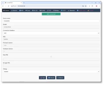
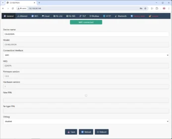
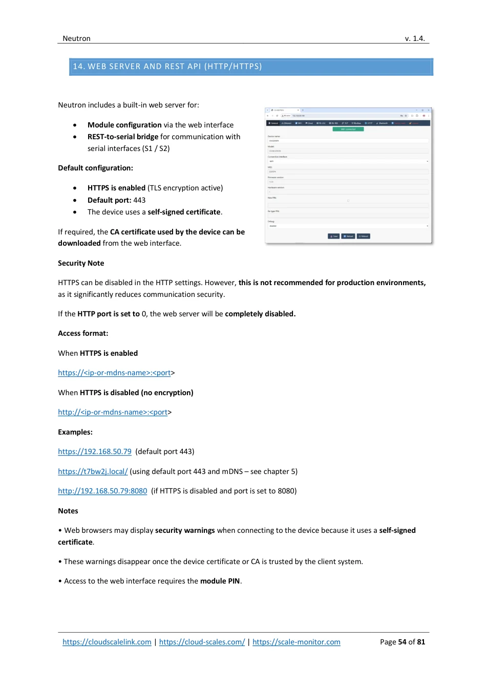
- Module configuration via the web interface • REST-to-serial bridge for communication with serial interfaces (S1 / S2)
Default configuration:
- HTTPS is enabled (TLS encryption active) • Default port: 443 • The device uses a self-signed certificate .
If required, the CA certificate used by the device can be downloaded from the web interface.
Security Note
HTTPS can be disabled in the HTTP settings. However, this is not recommended for production environments, as it significantly reduces communication security.
If the HTTP port is set to 0, the web server will be completely disabled.
Access format:
When HTTPS is enabled
https://<ip-or-mdns-name>:<port >
When HTTPS is disabled (no encryption)
http://<ip-or-mdns-name>:<port >
Examples:
https://192.168.50.79 (default port 443)
https://t7bw2j.local/ (using default port 443 and mDNS – see chapter 5)
http://192.168.50.79:8080 (if HTTPS is disabled and port is set to 8080)
Notes
- Web browsers may display security warnings when connecting to the device because it uses a self-signed certificate .
- These warnings disappear once the device certificate or CA is trusted by the client system.
- Access to the web interface requires the module PIN .
View original page 54 — diagrams and layout
14.1. TLS CERTIFICATE
Neutron supports the use of custom TLS certificates for the built-in web server. This allows you to replace the default self-signed certificate with a certificate issued by your organization or a trusted Certificate Authority (CA).
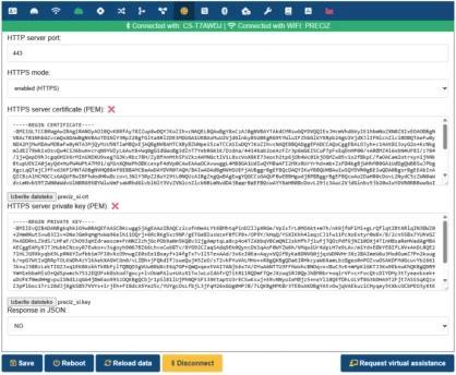
Using your own certificate can eliminate browser security warnings and ensure the device complies with internal security policies.
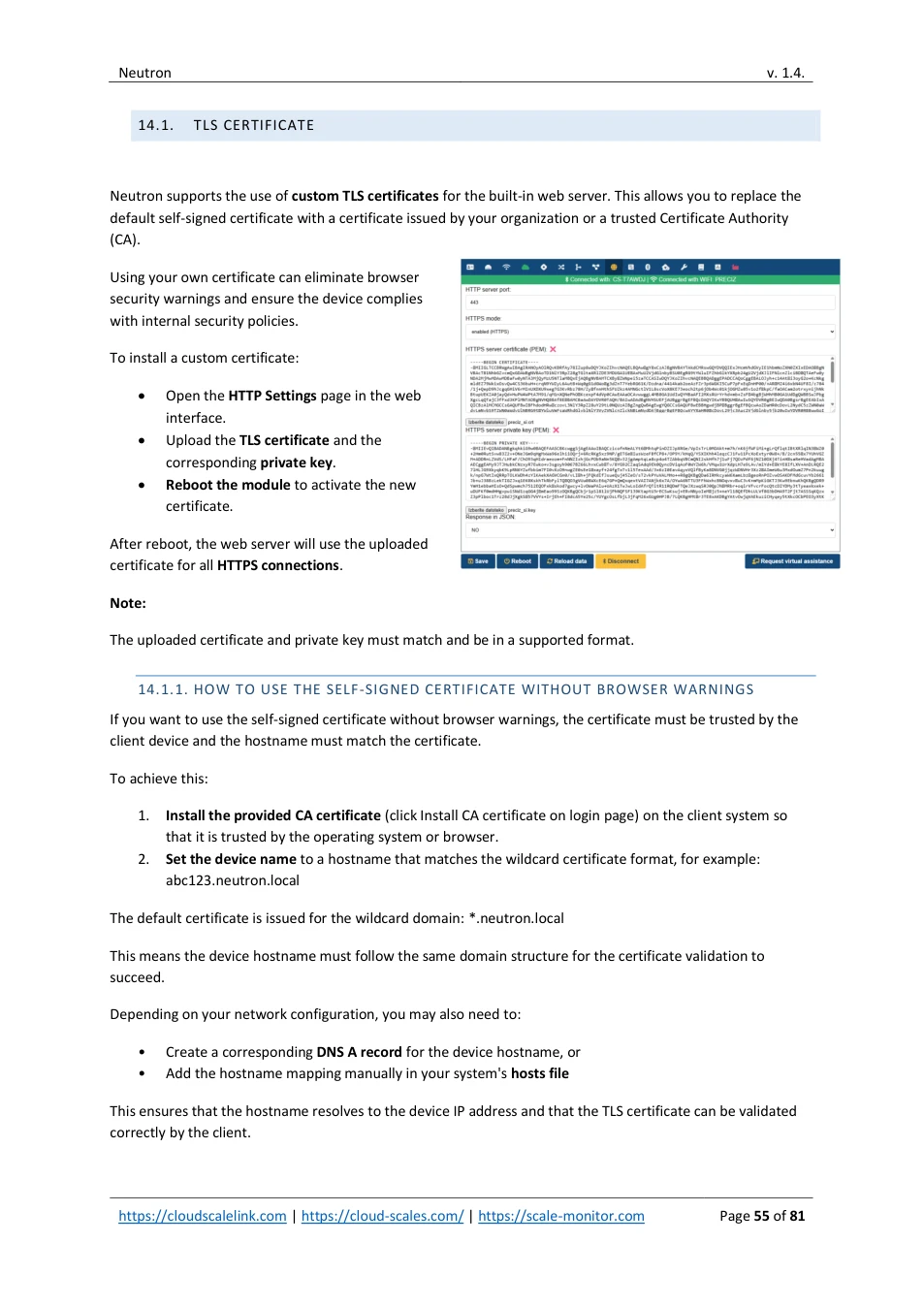
To install a custom certificate:
- Open the HTTP Settings page in the web interface. • Upload the TLS certificate and the corresponding private key . • Reboot the module to activate the new certificate.
After reboot, the web server will use the uploaded certificate for all HTTPS connections .
Note:
The uploaded certificate and private key must match and be in a supported format.
14.1.1. HOW TO USE THE SELF-SIGNED CERTIFICATE WITHOUT BROWSER WARNINGS
If you want to use the self-signed certificate without browser warnings, the certificate must be trusted by the client device and the hostname must match the certificate.
To achieve this:
1. Install the provided CA certificate (click Install CA certificate on login page) on the client system so that it is trusted by the operating system or browser. 2. Set the device name to a hostname that matches the wildcard certificate format, for example: abc123.neutron.local
The default certificate is issued for the wildcard domain: *.neutron.local
This means the device hostname must follow the same domain structure for the certificate validation to succeed.
Depending on your network configuration, you may also need to:
- Create a corresponding DNS A record for the device hostname, or • Add the hostname mapping manually in your system's hosts file
This ensures that the hostname resolves to the device IP address and that the TLS certificate can be validated correctly by the client.
View original page 55 — diagrams and layout
14.2. REST
Neutron provides a REST interface that can be used as a bridge to the serial ports or scale in case you use IO board.
To enable REST communication, you must set the serial redirect mode to HTTP. For scale you must set scale interface to HTTP.
If serial redirect is not enabled and a REST URL is accessed, the server will respond with “404 Not Found”. Same is valid, if scale interface is not set to HTTP the response will be “404 Not Found”.
Paths are addressed as follows:
- S1 for UART / RS-232 • S2 for RS-485 • SC for scale
After a request is sent, Neutron waits for a response from the serial port /scale for up to 5 seconds.
If a response is received, it is returned as the HTTP response body.
If no response is received within the timeout, the response body will contain:
[no serial response] for serial port or [no scale response] for scale
14.2.1. REST TOKEN
Neutron supports additional security by using token. In this case for both GET and POST you must provide tok parameter for example:
Without token:
http://10.20.10.23/SC/?cmd=SXI
With token which if set to Sc4l3M0n10r$2026# you will have to call:
https://10.20.10.23/SC/?cmd=SXI&tok=Sc4l3M0n10r$2026#
Token can be freely set under HTTP tab in module settings. Please note that token length can be maximum 128 characters and use only ASCII characters with control characters for HTML in GET method such as &,=,/.
View original page 56 — diagrams and layout
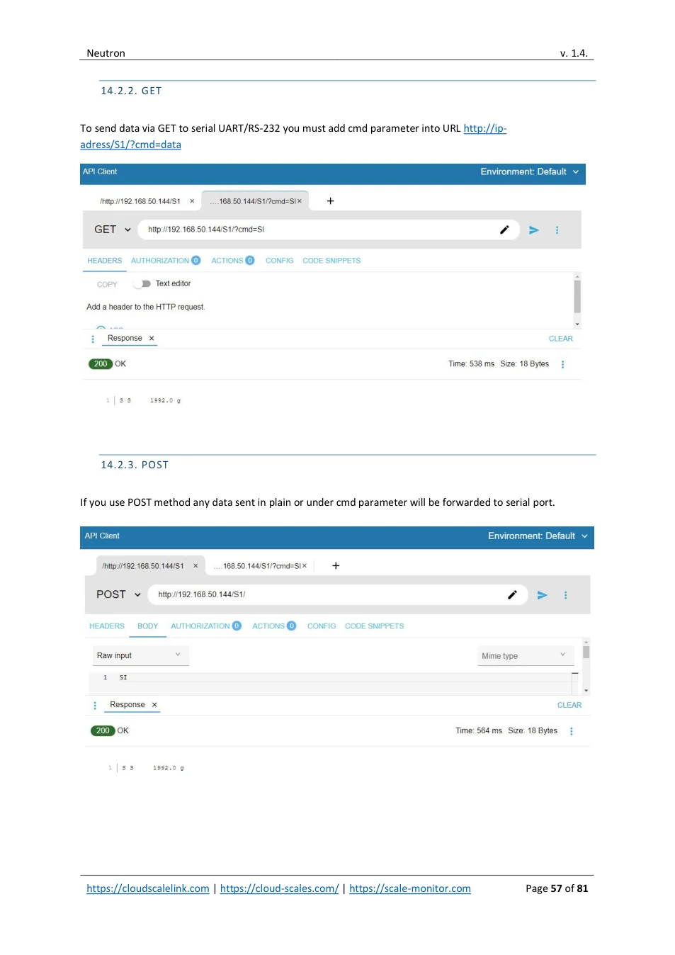
14.2.2. GET
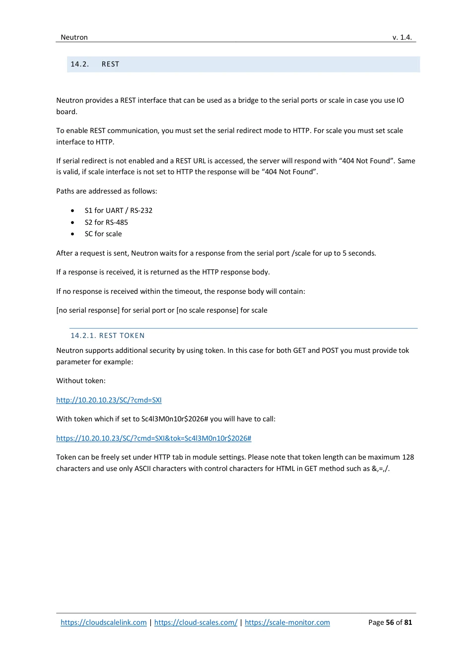
To send data via GET to serial UART/RS-232 you must add cmd parameter into URL http://ip- adress/S1/?cmd=data
14.2.3. POST
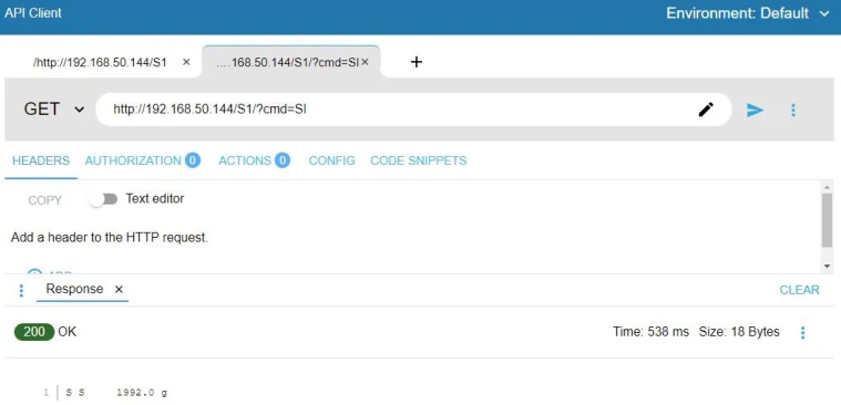
If you use POST method any data sent in plain or under cmd parameter will be forwarded to serial port.
View original page 57 — diagrams and layout
15. BLUETOOTH
Under Bluetooth settings you can set if Bluetooth interface is enabled or disabled.
If you want to use serial port via Bluetooth bridge you must set under serial redirect Bluetooth on the serial port that you want to redirect.
For serial port redirection you can also set string terminator.
15.1. BLUETOOTH BLE GATT
CloudScaleLink Neutron communicates over Bluetooth Low Energy using a custom BLE serial communication service.
To connect to Neutron over BLE, the application must use the following GATT UUIDs:
Service UUID : 49535343-fe7d-4ae5-8fa9-9fafd205e455
Write characteristic UUID: 49535343-8841-43f4-a8d4-ecbe34729bb3
Notify characteristic UUID: 49535343-1e4d-4bd9-ba61-23c647249616
The external device must:
1. Scan for BLE devices advertising service: 49535343-fe7d-4ae5-8fa9-9fafd205e455 2. Connect to the Neutron BLE device. 3. Open the primary service: 49535343-fe7d-4ae5-8fa9-9fafd205e455 4. Write commands to characteristic: 49535343-8841-43f4-a8d4-ecbe34729bb3 5. Subscribe to notifications from characteristic: 49535343-1e4d-4bd9-ba61-23c647249616
15.2. DEBUGGING VIA BLUETOOTH
Neutron provides real-time debugging over Bluetooth.
To enable Bluetooth debugging, open General Settings and set the debug interface to Bluetooth.
After enabling Bluetooth debugging, reboot the module.
During startup, the RGB indicator will blink blue, indicating that Neutron is waiting for a Bluetooth connection.
While waiting, Neutron does not start Wi-Fi, Ethernet, the IO board, or other interfaces. This allows all startup messages to be captured from the very beginning.
Neutron waits up to 30 seconds for a Bluetooth connection.
If no connection is established within this time, the module continues the normal boot process. In this case, debug messages will still be available after you connect.
View original page 58 — diagrams and layout
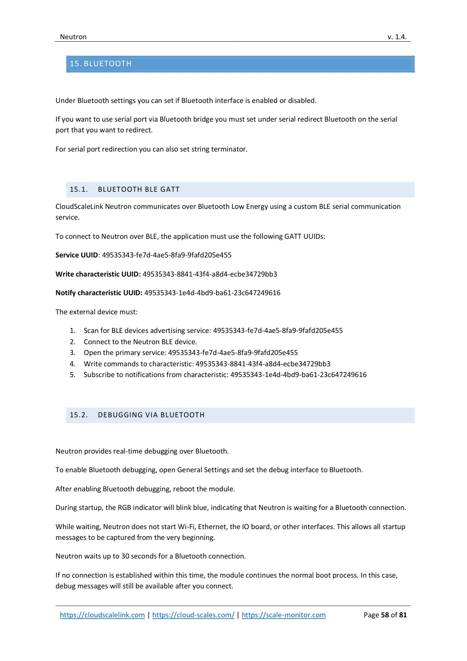
Note: Bluetooth debugging is available only through the BLE utility at:
https://apps.scale-monitor.com/
Once connected via Bluetooth, real-time debugging and remote support are possible even if Neutron is not connected to the internet.
You can see debug messages under Bluetooth tab of BLE utility:
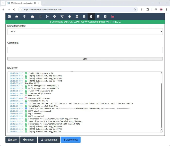
15.3. DEBUG SERIAL PORT REDIRECTION
To debug or test serial port redirection, enter the command or data into the Command field under Bluetooth tab and press the Send button.
The data will be forwarded to the serial port which has redirection set to Bluetooth.
Any response received from the serial device will be displayed in the Received field.
View original page 59 — diagrams and layout
16. TCP
Under the TCP tab you can configure TCP communication settings.
First, select the TCP connection type which can be:
- Server, • Client, • Server&client
16.1. SERVER MODE
In server mode, Neutron listens for incoming connections from external programs or systems.
You must specify the TCP port on which Neutron will listen.
The default TCP port is 10010.
16.1.1. TCP SERVER PORT EXCLUSIVE
When TCP server port exclusive mode is enabled, Neutron will accept only one TCP connection at a time.
If a connection is already established, any new incoming connection will be rejected.
When TCP server port exclusive mode is disabled, a new incoming connection will be accepted and any existing connection will be disconnected.
16.2. CLIENT MODE
In client mode, Neutron actively establishes a TCP connection to an external system.
You must enter the destination IP address and TCP port.
Neutron continuously monitors the TCP connection.
If the connection is lost, for example due to Wi-Fi signal loss or server unavailability, Neutron will automatically attempt to reconnect until the connection is restored.
16.3. TCP BRIDGE TO CLOUD
If you want to redirect TCP communication to the cloud, you can enable the TCP bridge to cloud feature.
When enabled, all data received on the TCP connection, whether operating in server or client mode, will be forwarded to the cloud and vice versa.
View original page 60 — diagrams and layout
Cloud redirection can be enabled independently for server mode and client mode.
This feature is especially useful when connecting Ethernet or Wi-Fi devices, such as scales or label printers (for example Zebra printers), directly to the cloud when these devices support only TCP communication.
Detailed information about the TCP-to-cloud bridge is available in the CSL API documentation.
16.3.1. CONNECT ETHERNET OR WI-FI PRINTER TO SCALE MONITOR CLOUD
To connect an Ethernet or Wi-Fi printer to the cloud, open the TCP settings and set the TCP mode to Client.
Under Client settings, enter the printer IP address and TCP port.
The most commonly used printer port is 9100.
If you do not know the printer IP address, refer to the printer manufacturer’s documentation.
For example, many Zebra printers allow printing or displaying the network configuration by pressing a specific key combination. The exact procedure depends on the printer model.
In Scale Monitor, open Settings and enable the option “Use bridge mode” under Label Printer settings.
If the same CloudScaleLink module is used for both the scale and the label printer, enter the same MID and PIN that are configured for the scale connection.
16.3.2. PRINTER CONFIRMATION MESSAGES (ZEBRA)
If you want to receive a confirmation message in Scale Monitor indicating that a label was printed successfully, or alert message such as out of labels, no ribbon, cover opened etc. you must change the TCP configuration.
In TCP settings, set the TCP type to Server & Client.
Under Server settings, enable the option Bridge to cloud.
Next, open the Zebra printer configuration page by entering the printer IP address into a web browser.
View original page 61 — diagrams and layout
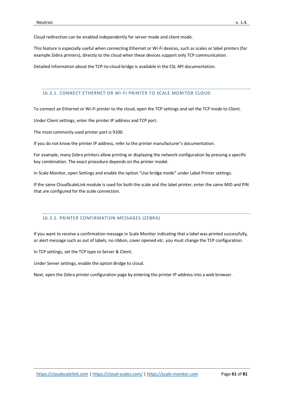
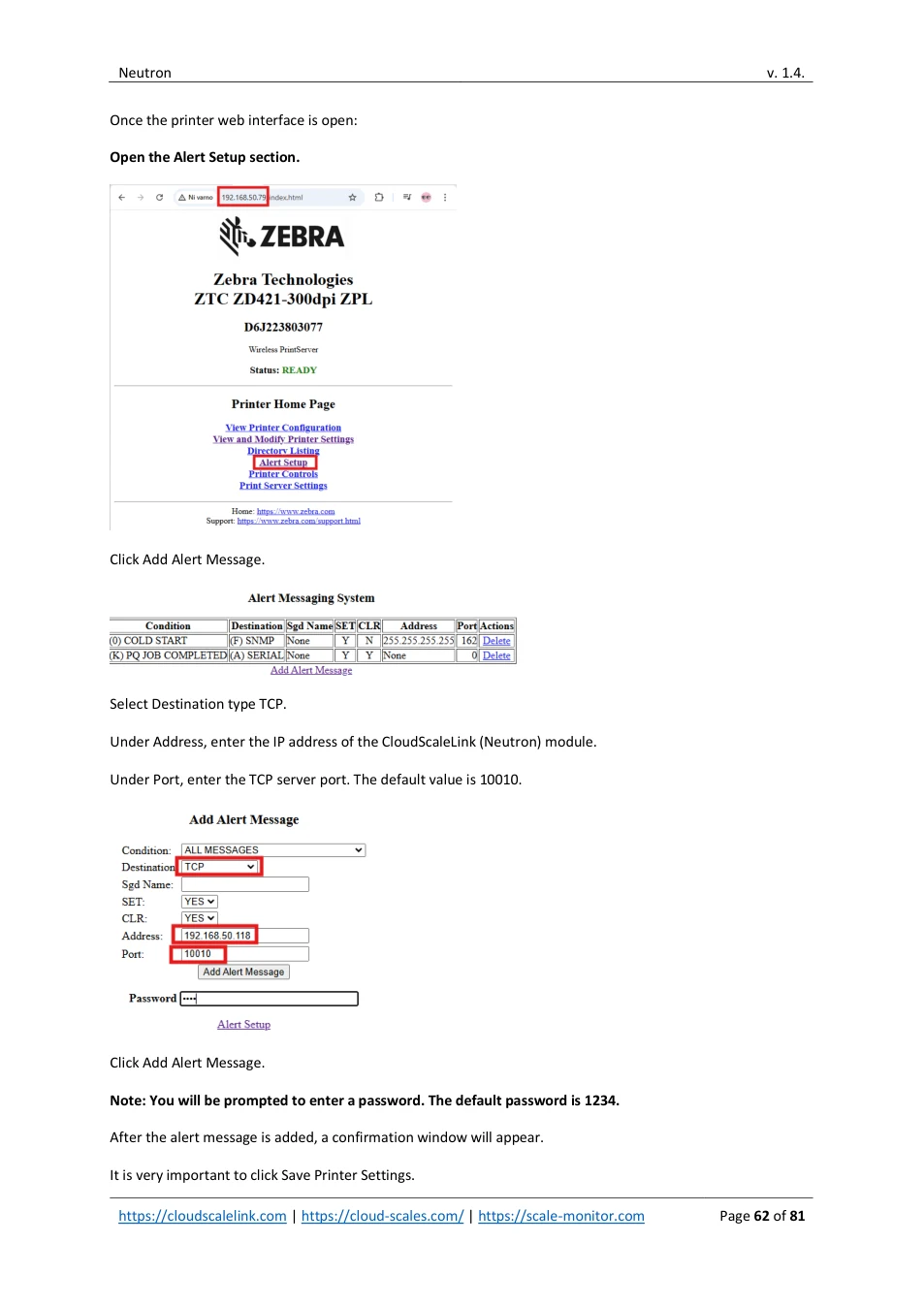
Once the printer web interface is open:
Open the Alert Setup section.
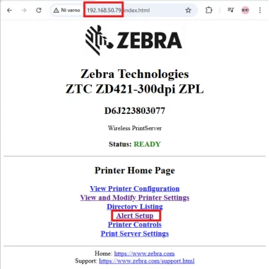
Click Add Alert Message.
Select Destination type TCP.
Under Address, enter the IP address of the CloudScaleLink (Neutron) module.
Under Port, enter the TCP server port. The default value is 10010.
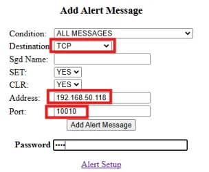
Click Add Alert Message.
Note: You will be prompted to enter a password. The default password is 1234.
After the alert message is added, a confirmation window will appear.
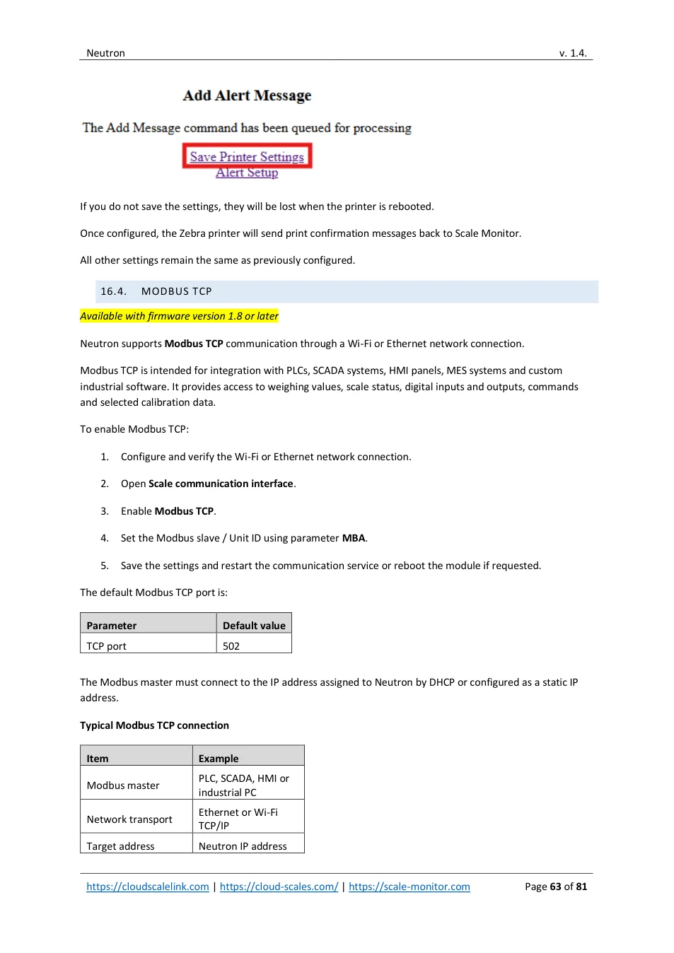
It is very important to click Save Printer Settings.
View original page 62 — diagrams and layout
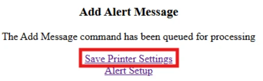
If you do not save the settings, they will be lost when the printer is rebooted.
Once configured, the Zebra printer will send print confirmation messages back to Scale Monitor.
All other settings remain the same as previously configured.
16.4. MODBUS TCP
Available with firmware version 1.8 or later
Neutron supports Modbus TCP communication through a Wi-Fi or Ethernet network connection.
Modbus TCP is intended for integration with PLCs, SCADA systems, HMI panels, MES systems and custom industrial software. It provides access to weighing values, scale status, digital inputs and outputs, commands and selected calibration data.
To enable Modbus TCP:
1. Configure and verify the Wi-Fi or Ethernet network connection.
2. Open Scale communication interface .
3. Enable Modbus TCP .
4. Set the Modbus slave / Unit ID using parameter MBA .
5. Save the settings and restart the communication service or reboot the module if requested.
The default Modbus TCP port is:
| Parameter | Default value | ||||
|---|---|---|---|---|---|
| TCP port | 502 |
The Modbus master must connect to the IP address assigned to Neutron by DHCP or configured as a static IP address.
Typical Modbus TCP connection
| Item | Example | ||||
|---|---|---|---|---|---|
| Modbus master | PLC, SCADA, HMI or industrial PC | ||||
| Network transport | Ethernet or Wi-Fi TCP/IP | ||||
| Target address | Neutron IP address |
View original page 63 — diagrams and layout
| Service port | 502 |
|---|---|
| Unit ID | MBA value; default 1 |
For industrial installations, Ethernet is recommended whenever a wired network connection is available. Wi-Fi may introduce network-dependent latency and should be validated under actual operating conditions.
Note: Modbus TCP can be used together with other enabled scale communication interfaces (see section 7.1). For example, Neutron can communicate with a scale through RS-232 or RS-485 while a PLC reads weighing data through Modbus TCP.
For supported Modbus functions, register addresses, weight data format, digital I/O control and command handling, refer to the separate CloudScale Neutron Modbus User Manual: https://apps.scale-monitor.com/files/Neutron/CS-NEUTRON_EN_Modbus_latest.pdf
The document describes both Modbus RTU and Modbus TCP using the same logical register map
View original page 64 — diagrams and layout
17. IO BOARD
The IO board provides the following features:
- 4-channel 24-bit sigma-delta ADC with up to 4,800 conversions per second • 6 digital inputs (can also be used as counters up to 1,000 Hz) • 6 digital outputs
Note: Digital inputs and outputs can be configured only using the BLE utility or the Cloud interface.
Note: if you need to control outputs via command or read state of inputs, counter values etc. please see CSL API documentation.
17.1. DIGITAL INPUTS
Each digital input can be configured either as an ON/OFF input or as a counter.
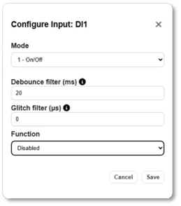
Using the Mode setting, you can select whether the input behaves as an ON/OFF switch or as a counter.
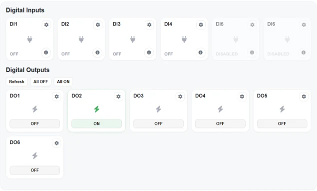
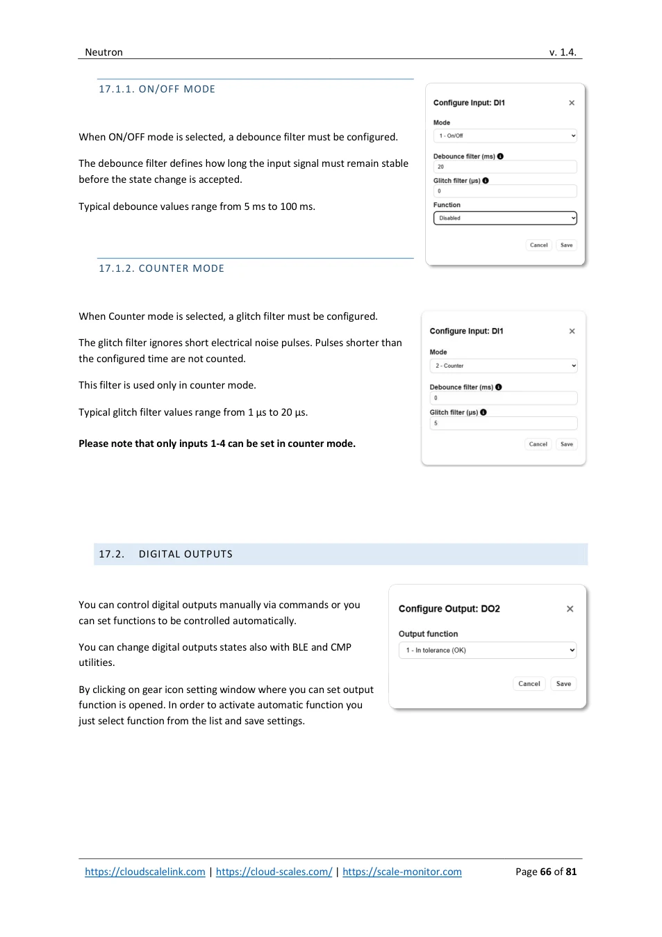
Under IO tab you will see input&outputs dashboard where current states are shown. By clicking on gear icon you can setup settings.
View original page 65 — diagrams and layout
17.1.1. ON/OFF MODE
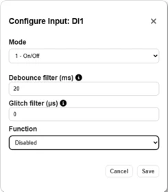
When ON/OFF mode is selected, a debounce filter must be configured.
The debounce filter defines how long the input signal must remain stable before the state change is accepted.
Typical debounce values range from 5 ms to 100 ms.
17.1.2. COUNTER MODE
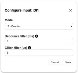
When Counter mode is selected, a glitch filter must be configured.
The glitch filter ignores short electrical noise pulses. Pulses shorter than the configured time are not counted.
This filter is used only in counter mode.
Typical glitch filter values range from 1 µs to 20 µs. Please note that only inputs 1-4 can be set in counter mode.
17.2. DIGITAL OUTPUTS
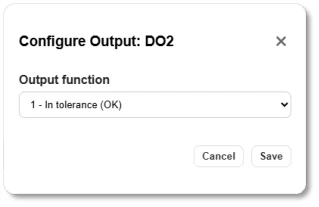
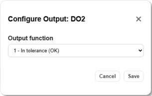
You can control digital outputs manually via commands or you can set functions to be controlled automatically.
You can change digital outputs states also with BLE and CMP utilities.
By clicking on gear icon setting window where you can set output function is opened. In order to activate automatic function you just select function from the list and save settings.
View original page 66 — diagrams and layout
18. SCALE
The IO board features a 4-channel 24 bit ADC with up to 4.800 conversions per second.
Each ADC channel can be configured as an independent scale.
For communication with the scale, the following interfaces are supported:
- UART / RS-232 • RS-485 • Bluetooth BLE 5.0 • Cloud connection using MQTT v3.1 over TCP or secure WSS (certificate required) • WebSocket (WS unencrypted and WSS secure are available) • HTTP (REST API)


The scale communication protocol is described in the CloudScale Communication Protocol (CSCP) manual. You can download latest version on: https://apps.scale-monitor.com
18.1. DISPLAY OVERVIEW
In calibration menu display has following visualization:
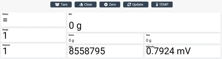
The calibration menu provides the following visual information:
- Status - The status indicator shows the current weighing condition:
o
= stable weight
o
~ unstable weight
o
UL: underload
o
OL: overload
•
Range - Displays the active weighing range (1 to 3), depending on the scale configuration and current
gross weight.
•
Channel - Displays the active ADC channel (1 to 4), depending on the selected channel.
•
ADC Value - Shows the raw ADC converter value based on the current load cell signal.
•
Millivolts - Displays the measured signal from the load cell(s) in millivolts.
View original page 67 — diagrams and layout
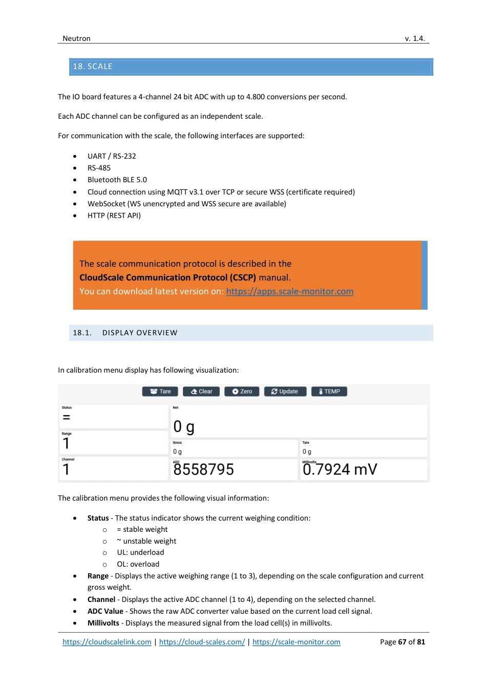
The following functions can be executed directly from the calibration menu:
- Tare • Clear tare • Zero • Temperature
By pressing the TEMP button, the ADC internal temperature reading is displayed.
Note:
When temperature is being measured, ADC conversion for weighing is temporarily suspended.
18.2. CHANNEL SWITCHING
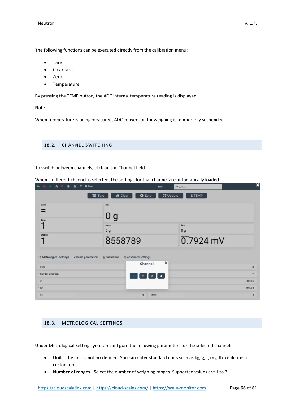
To switch between channels, click on the Channel field.
When a different channel is selected, the settings for that channel are automatically loaded.

18.3. METROLOGICAL SETTINGS
Under Metrological Settings you can configure the following parameters for the selected channel:
- Unit - The unit is not predefined. You can enter standard units such as kg, g, t, mg, lb, or define a custom unit. • Number of ranges - Select the number of weighing ranges. Supported values are 1 to 3.
View original page 68 — diagrams and layout
- Range type - Select how the scale behaves across ranges:
o
Multi-division: the scale always returns values using the same division.
o
Multi-range: the scale returns values using the division of the currently active range (highest
interval).
•
Divisions (d1–d3) - d1 defines the division for range 1, d2 for range 2, and d3 for range 3.
•
Maximum values (Max1–Max3) - Max1 defines the maximum weight for range 1, Max2 for range 2,
and Max3 for range 3.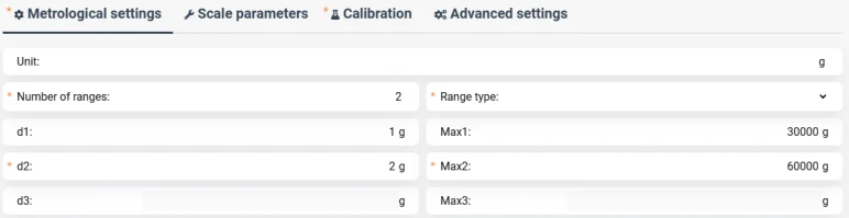
18.4. SCALE PARAMETERS
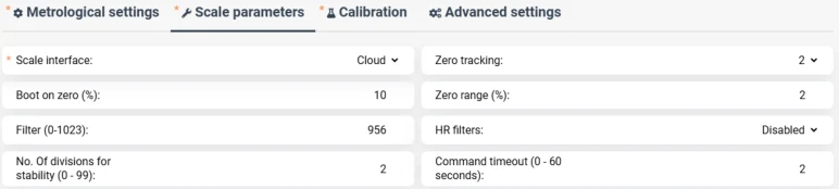
In the Scale Parameters menu you can configure the following settings:
- Scale interface - Select the interface used to communicate with the scale. For Scale Monitor operation, set the interface to Cloud, RS-232, or Bluetooth, depending on your Scale Monitor configuration. • Zero tracking - Select the zero-tracking range in divisions. Available values: Disabled, 1/4, 1/2, 1, 2, 4, 8, or 10 divisions. • Boot on zero - Defines the percentage of the scale maximum that can be automatically zeroed when the module powers on. • Zero range - Defines the zeroing range, expressed as a percentage of the scale maximum, that can be zeroed after executing a zero command. • Filter - Defines the digital filtering level. Filter value 0 disables filtering and allows the maximum conversion rate of 4,800 Hz. Higher filter values provide a more stable reading but increase stabilization time. • HR filter - High-resolution filter that provides additional noise reduction. Using this filter improves stability but requires a longer stabilization time. • Number of divisions for stability - Defines how many divisions the weight may change while still being considered stable. If set to 0, the weight is always considered stable. • Command timeout - Defines the maximum time allowed for a command to be executed. For example, if the timeout is set to 2 seconds and a tare command is sent, the scale will wait up to 2 seconds for the weight to become stable. If stabilization takes longer than the configured timeout, a timeout error occurs and the command is cancelled.
View original page 69 — diagrams and layout
View original page 70 — diagrams and layout
18.5. CALIBRATION
The Calibration tab is used to calibrate the scale.
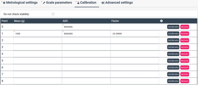
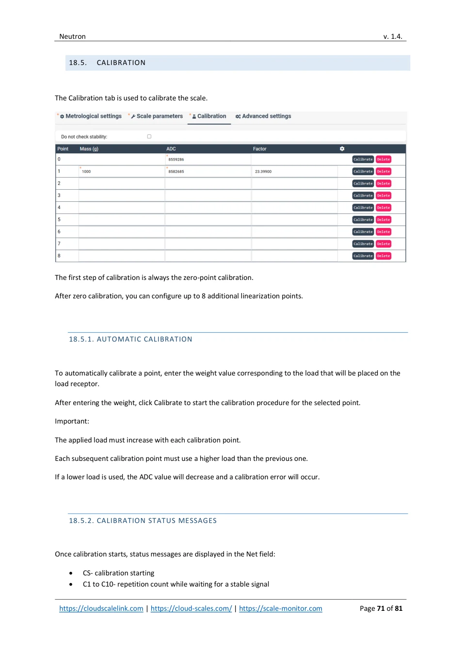
The first step of calibration is always the zero-point calibration.
After zero calibration, you can configure up to 8 additional linearization points.
18.5.1. AUTOMATIC CALIBRATION
To automatically calibrate a point, enter the weight value corresponding to the load that will be placed on the load receptor.
After entering the weight, click Calibrate to start the calibration procedure for the selected point.
Important:
The applied load must increase with each calibration point.
Each subsequent calibration point must use a higher load than the previous one.
If a lower load is used, the ADC value will decrease and a calibration error will occur.
18.5.2. CALIBRATION STATUS MESSAGES
Once calibration starts, status messages are displayed in the Net field:
- CS- calibration starting • C1 to C10- repetition count while waiting for a stable signal
View original page 71 — diagrams and layout
- CF- calibration finished successfully • CE- calibration error
If the signal is still not stable after 10 repetitions, a calibration error (-CE-) will occur.
In this case, you can either repeat the calibration point and provide more stable enviroment or enable the option “Do not check stability”.
When this option is enabled, the scale will not verify signal stability, allowing the calibration point to be stored even if the signal is unstable.
18.5.3. MANUAL CALIBRATION
The scale can also be calibrated or fine-tuned manually by entering ADC values and calibration factors directly.
18.6. ADVANCED SETTINGS
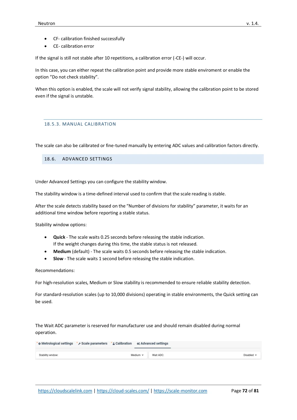
Under Advanced Settings you can configure the stability window.
The stability window is a time-defined interval used to confirm that the scale reading is stable.
After the scale detects stability based on the “Number of divisions for stability” parameter, it waits for an additional time window before reporting a stable status.
Stability window options:
- Quick - The scale waits 0.25 seconds before releasing the stable indication. If the weight changes during this time, the stable status is not released. • Medium (default) - The scale waits 0.5 seconds before releasing the stable indication. • Slow - The scale waits 1 second before releasing the stable indication.
Recommendations:
For high-resolution scales, Medium or Slow stability is recommended to ensure reliable stability detection.
For standard-resolution scales (up to 10,000 divisions) operating in stable environments, the Quick setting can be used.
The Wait ADC parameter is reserved for manufacturer use and should remain disabled during normal operation.

View original page 72 — diagrams and layout
19. CLOUD MANAGEMENT PLATFORM (CMP)
By registering at https://register.scale-monitor.com , you can manage and monitor all your modules using the Cloud Management Platform (CMP).
CMP allows you to manage all CloudScaleLink modules that have cloud management enabled and are connected to the internet.
Access is available from any web browser, anywhere in the world, using any device.
With CMP you can:
- Monitor Wi-Fi signal strength or Ethernet connection status • Test connectivity • Blink the module LEDs to identify a specific device when multiple modules are installed nearby • Remotely reboot the module • Change all module settings • Debug communication remotely
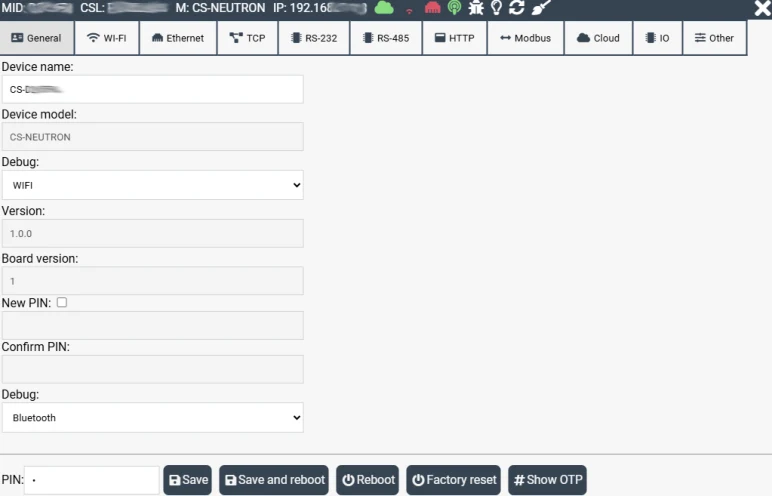
19.1. LIST OF MODULES
In CMP you will see all modules that you have activated in the Cloud Management Platform.
Through CMP you can centrally manage all your modules.
View original page 73 — diagrams and layout
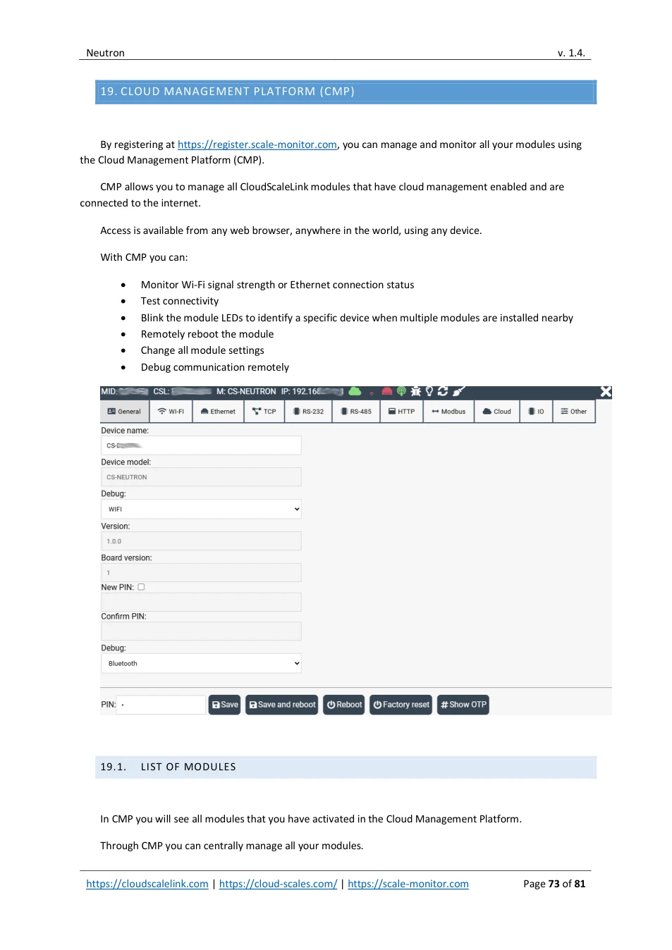
You can modify any module settingş, such as changing IP configuration, enabling or disabling DHCP, and other network or system parameters.
CMP allows real-time monitoring of all modules.
By clicking the “Ping all modules” button, you can request the current status of all modules simultaneously.
If any module is offline, it will be immediately indicated.
CMP also allows you to test and debug the connection with individual modules.
For more details, see the section “Debugging via CMP”.

19.2. MODULE ACTIVATION
To see and manage module you must activate module in CMP. Please note that, if you add scale in Scale Monitor module will be automatically activated in CMP.
To activate module after login, go to Menu → CloudScaleLink → Modules → Activate module
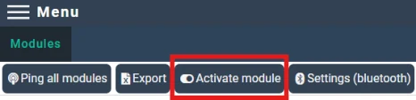
Into form enter MID and PIN of the module which are printed on the label of the module:
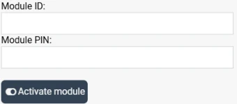
After entering module press Activate module and module will be added to the list of modules:
View original page 74 — diagrams and layout
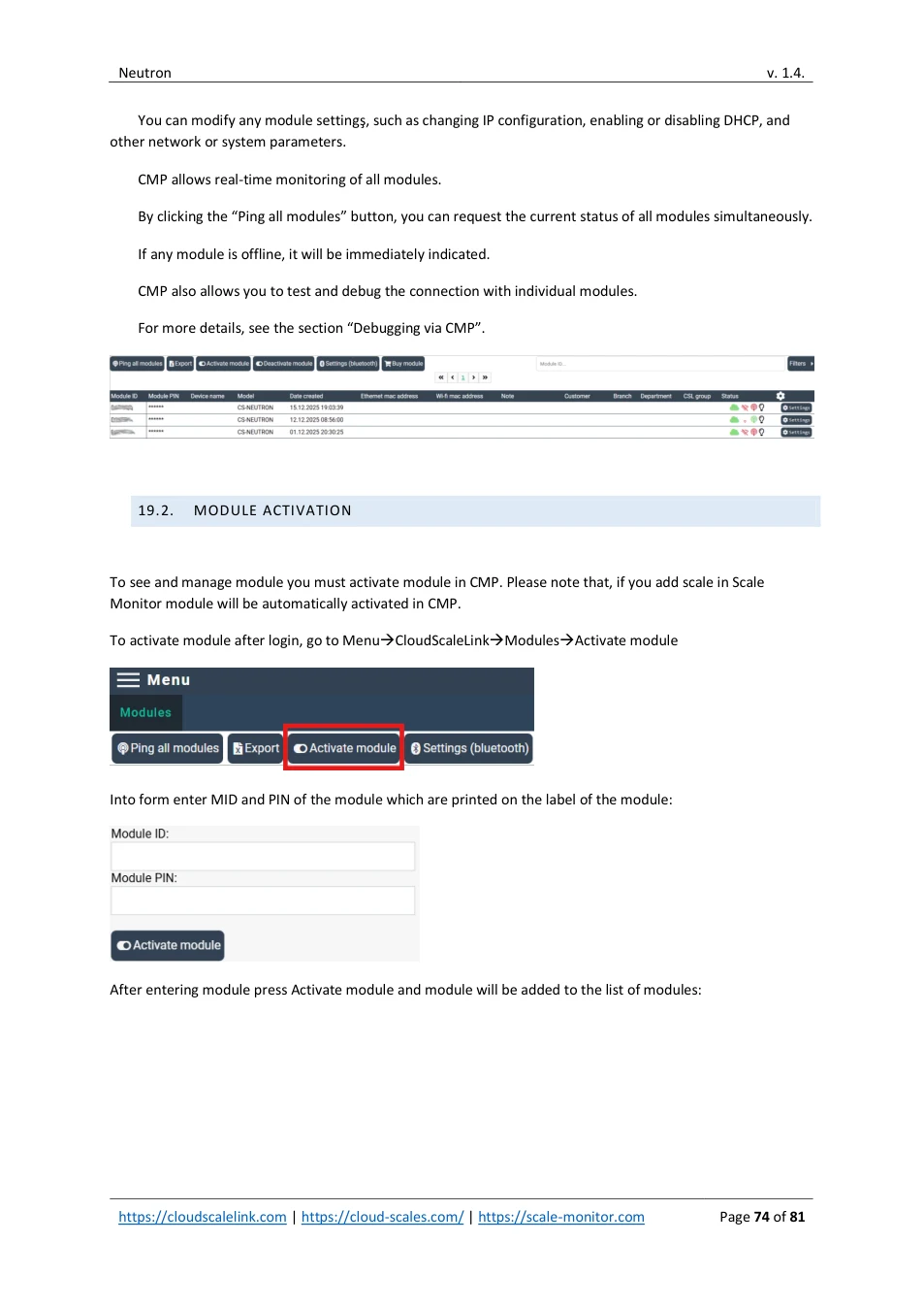
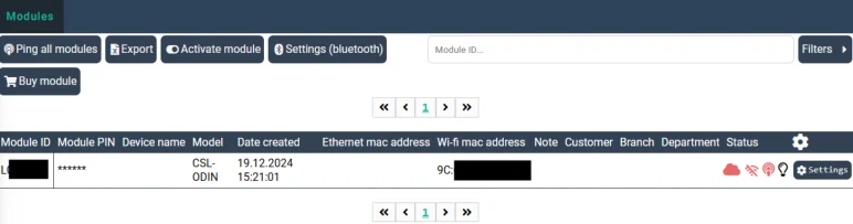
IMPORTANT: when you activate module inside your CMP nobody else will be able to activate this module inside their CMP until you deactivate it in your CMP.
19.3. MODULE DEACTIVATION
To deactivate module, click on deactivate module button and in the window enter module data and confirm deactivation by clicking Deactivate module button.
Afte deactivation module will be deleted from list of modules.
19.4. SETTINGS
If you click on Settings a settings window will open and connection with module if it is connected to the internet will be established:
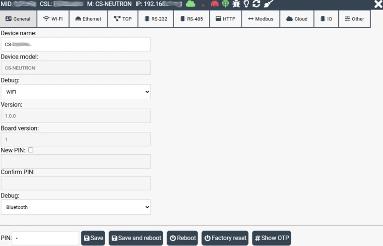
View original page 75 — diagrams and layout
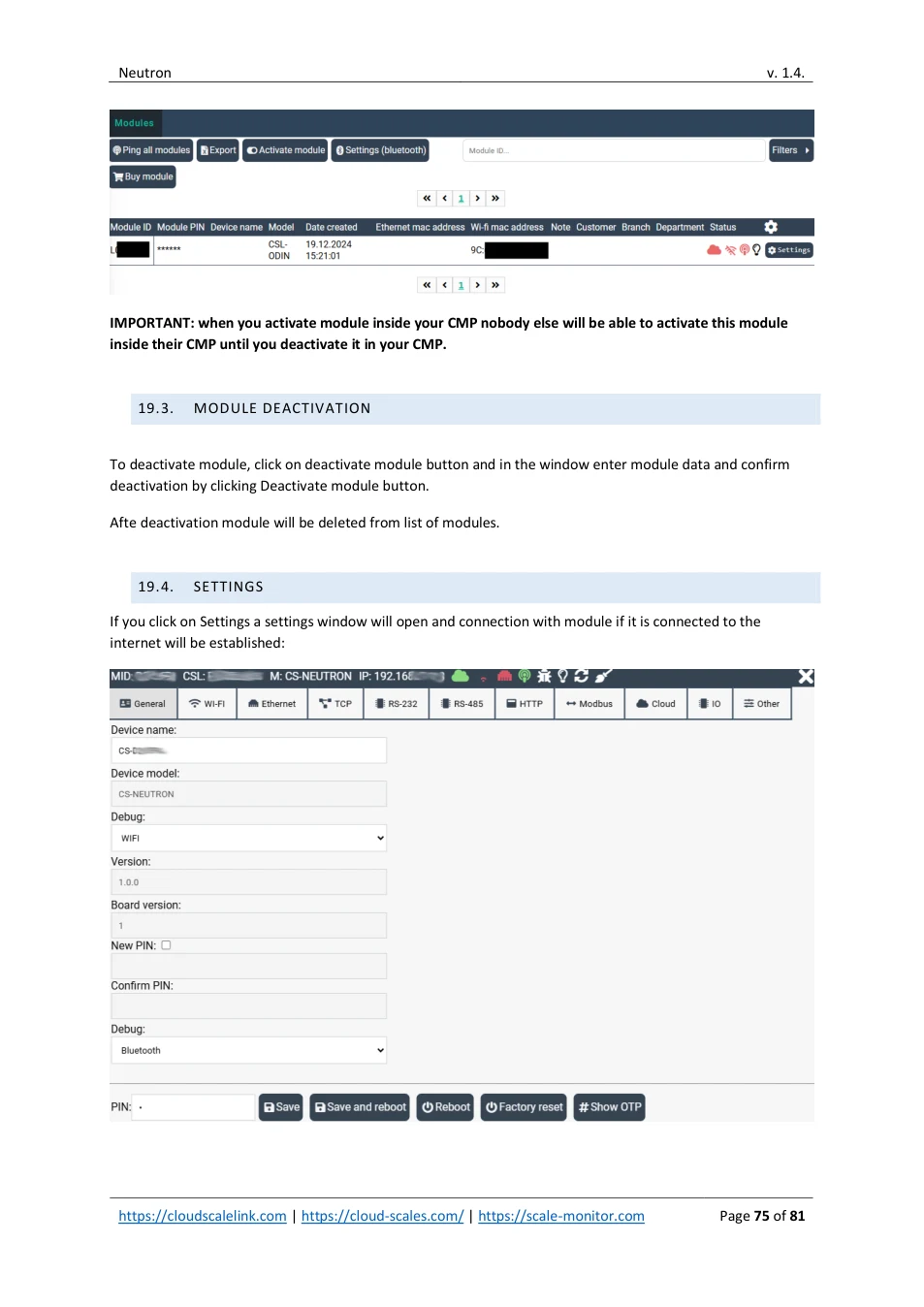
19.5. TOP BAR BUTTONS AND STATUSES
In the top bar you can see several status indicators and control buttons:

Cloud status
The cloud icon indicates the cloud connection status.
If the connection to the cloud is established, the icon is shown in green.
If the connection is not established, the icon is shown in red.

Wi-Fi status
For Wi-Fi modules, the Wi-Fi icon shows signal strength using colors:
- Green: excellent signal • Orange: good signal • Red: poor signal
If the module is not connected to the cloud, a crossed red Wi-Fi icon is displayed.


Ethernet status
For Ethernet modules, an Ethernet icon is shown:
- Green Ethernet icon: Ethernet connected • Red Ethernet icon: no Ethernet connection to the module

Ping button
When you click the Ping button, a ping request is sent to the module.
This allows you to verify that the module is online and responsive.

Identification button
When you click the identification (light) button, the button turns green and the module’s green LED starts blinking.
This helps you identify a specific module when multiple modules are installed at the same location.
Clicking the button again turns the green LED off.

Reload data button
Clicking the reload data button refreshes and reloads the module data from the cloud.

Debug button
Clicking the debug button opens the debug window.
For more information, see the section “Debugging via CMP”.
View original page 76 — diagrams and layout
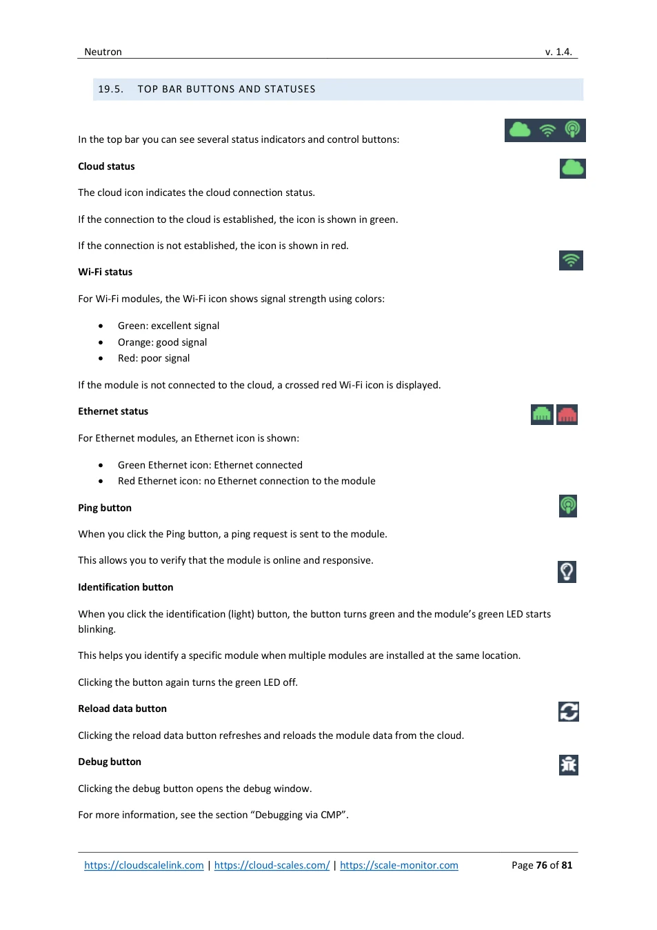
19.6. DEBUGGING VIA CMP
The built-in debugger allows you to view real-time communication between and module via RS-232 and the cloud, or between the device and any program it is connected to.
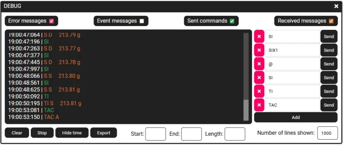
In the debug window, communication is displayed using different colors:
- Sent commands are shown in green • Received messages, including responses to sent commands, are shown in orange • Error messages are shown in pink
The built-in debugger also allows you to test your device by manually entering commands and sending them to the device.
Any response received from the device is displayed in the debug window.
The command panel is located on the right side of the debug window.
19.6.1. MANAGING COMMANDS IN DEBUG WINDOWS
To add command, click on add button and new field will appear:
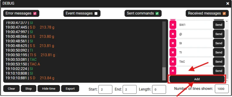
View original page 77 — diagrams and layout
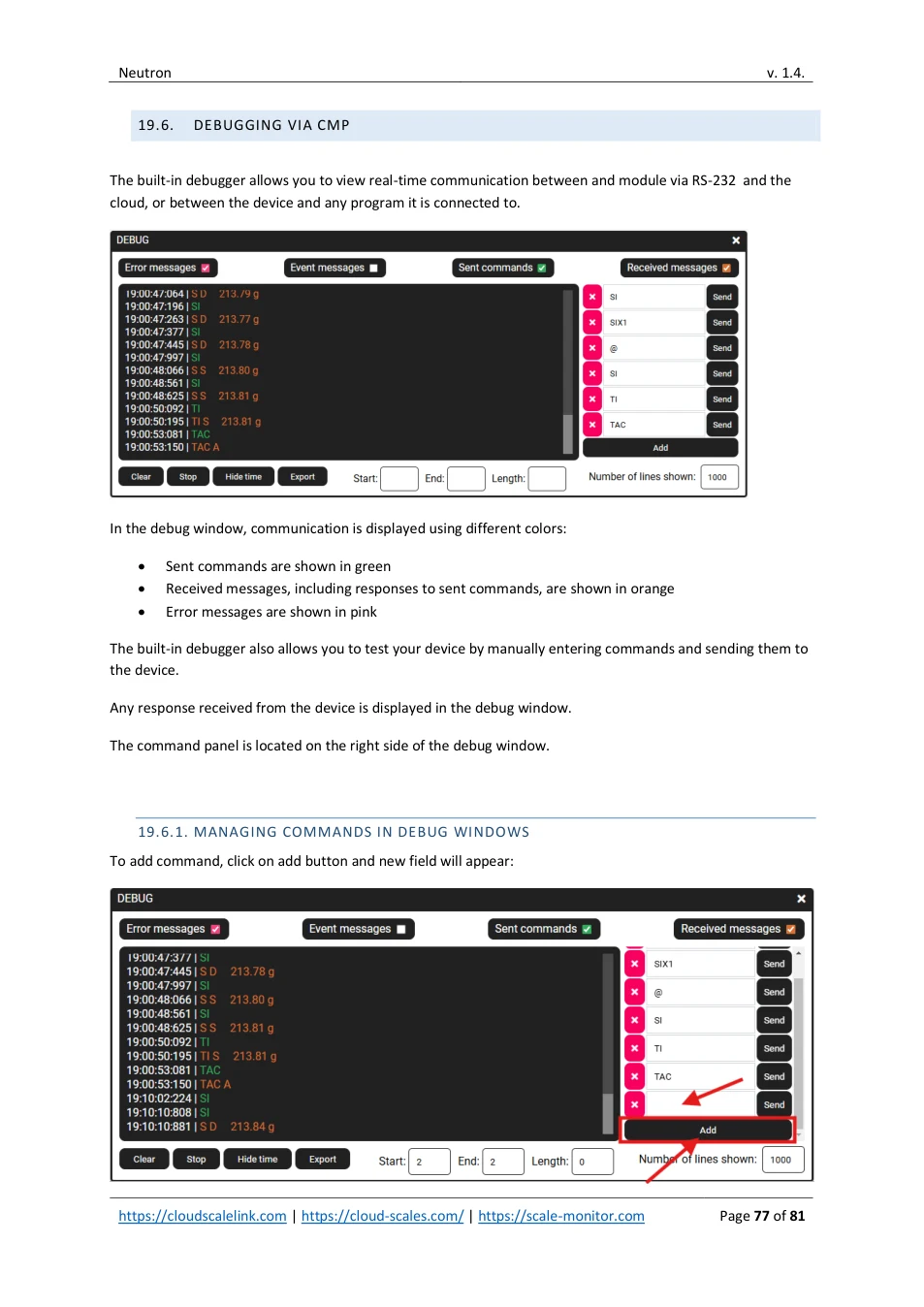
Into new field write new command and then you can send this command to device by clicking Send button next to the field into which you entered command.
To delete command, you just click on X button in front of the field.
20. SYSTEM RESOURCES
Under system resource section you can monitor uptime, CPU load, memory and number of WIFI/Ethernet disconnects and lost IP since boot.
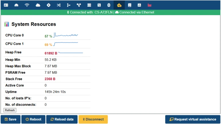
View original page 78 — diagrams and layout
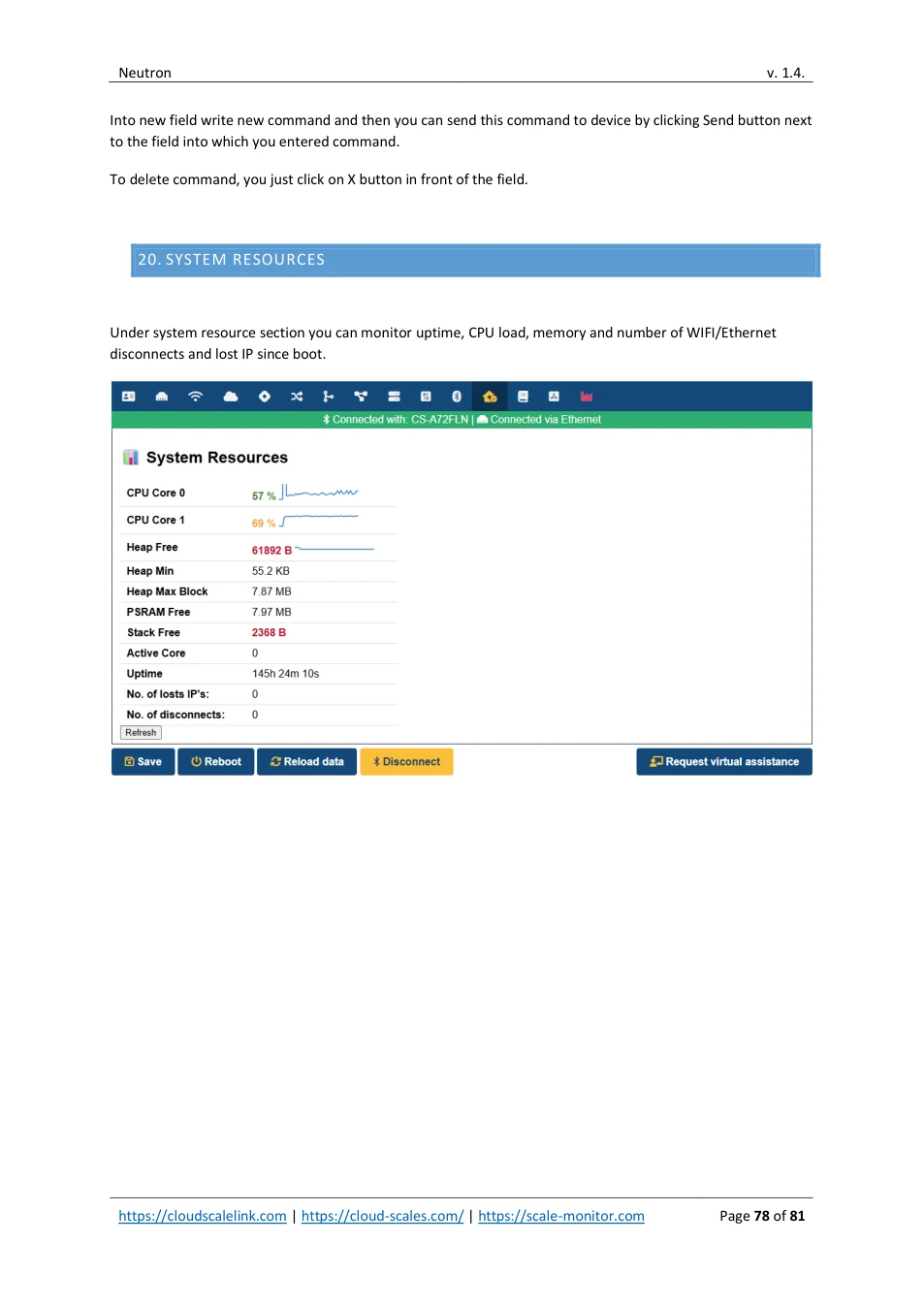
21. REMOTE VIRTUAL ASSISTANCE
In case you have troubles you may always use your phone or other device with Bluetooth and connect with Neutron. After connecting click request virtual assistance and someone from support will connect directly to module.
Once assistant will respond you will be able to chat with him while he will resolve your request.
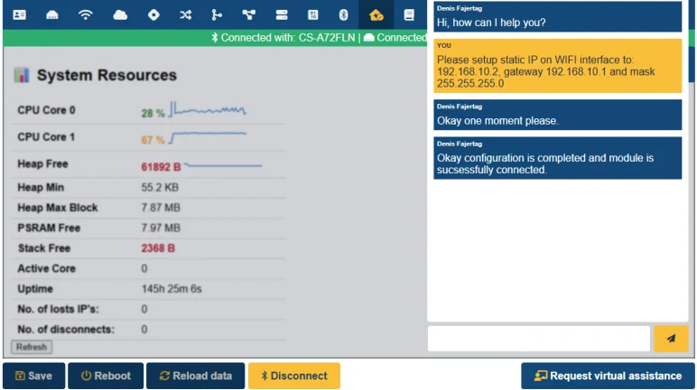
Please note that assistant can see and monitor Neutron.
View original page 79 — diagrams and layout
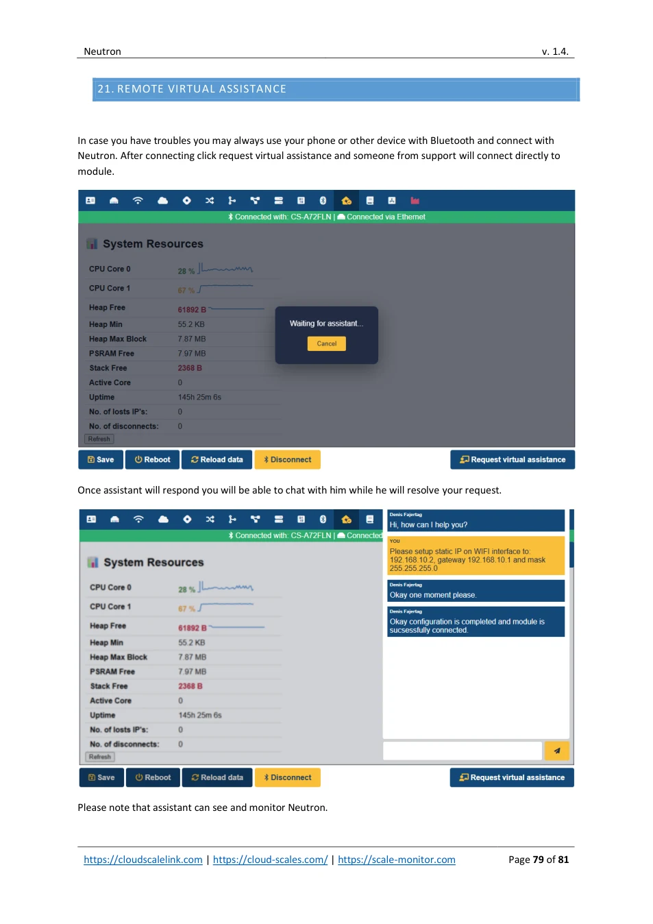
Access to settings is blocked during assistance to prevent any unwanted interaction from user. After assistance is completed you will gain full access again.
22. TROUBLESHOOTING
22.1. NEUTRON DOES NOT CONNECT TO WI-FI
If Neutron does not connect to a Wi-Fi network, there may be several possible causes. Please check the following:
- Verify that the SSID (Wi-Fi name) is entered correctly. • Verify that the password is entered correctly. Note: If Neutron is connecting to an open network, the password field must be empty. • If BSSID is configured, verify that it is set correctly. • Check that the Wi-Fi network is available and that the signal strength is sufficient. • Ensure that the Wi-Fi network operates on the 2.4 GHz band. Neutron does not support 5 GHz Wi-Fi. • Verify that an external antenna is properly connected. Neutron requires an external antenna for Wi-Fi operation.
22.2. SCANNING WI-FI NETWORSK DOES NOT WORK
If Neutron is searching for a Wi-Fi network (Wi-Fi is selected as the communication interface and the module is not yet connected), scanning for available Wi-Fi networks is not possible at the same time.
22.3. NEUTRON NOT CONNECTED TO CMP
If the module is not connected to the Cloud Management Platform (CMP), please check the following:
- Verify that Neutron is connected to Wi-Fi or Ethernet. • Check the RGB LED indicator:
o
Green: connected via Wi-Fi or Ethernet
o
Red: not connected
•
Verify that Neutron has a valid IP address.
If using Ethernet with DHCP enabled, a yellow LED indicates the module is waiting for an IP address.
•
Verify that Neutron has valid DNS settings.
Invalid or missing DNS configuration can prevent cloud connectivity even if the network connection is
established. If you do not have DNS available you can also enter IP address instead or URL into server
field.
•
If the IP address and DNS settings are correct, verify that Neutron can establish an internet connection
to the cloud.
Check the cloud status indicator in CMP or on the module interface.
View original page 80 — diagrams and layout
If the cloud connection is not established, ensure that outbound internet access is allowed and that firewall rules do not block the required ports.
View original page 81 — diagrams and layout