
NEUTRON NT · USER MANUAL
Neutron NT — user manual
From initial setup to weighing, piece counting, printing, saving records and configuring your scale.
1. Before you start
1.1 What is Neutron NT?
Neutron NT is a weighing terminal with a 7-inch touchscreen for displaying weight, piece counting, checkweighing, data capture and connecting a weighing station to other systems. The display and data fields can be adapted to your workflow. Available applications and accessories depend on the device configuration.
1.2 Display, housing and weighing channels
Field / label | Meaning and use |
|---|---|
Display | 7-inch IPS TFT LCD, 1,024 × 600 pixels, touch operation. |
Housing | AISI 304 stainless steel, IP67 protection. |
Weighing channels | Up to 4 weighing-platform channels, each with its own settings. The ADC is multiplexed: conversion takes place for one channel at a time. |
Connectivity | 2.4 GHz Wi-Fi, Bluetooth BLE and optional Ethernet; UART, RS-232 and RS-485 serial interfaces. |
Inputs and outputs | 6 configurable optically isolated digital inputs and 6 PhotoMOS outputs for process integration. |
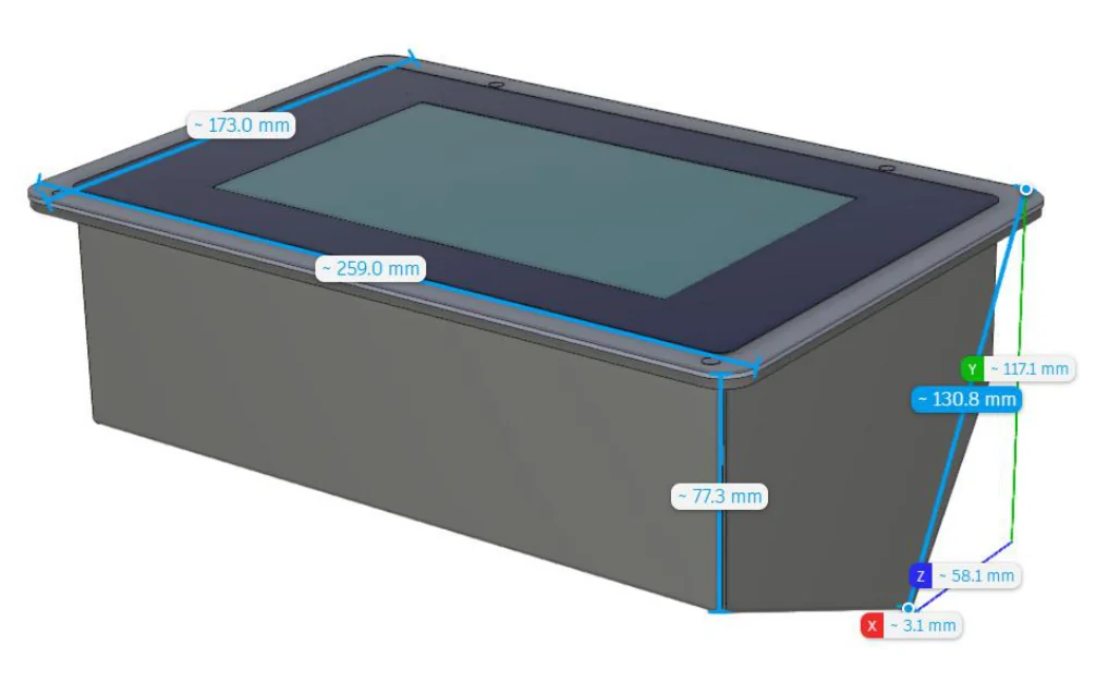
Neutron NT: housing, display and dimensions in millimetres.
1.3 Positioning and safe use
Place the weighing platform on a stable surface, clear of surrounding objects. Avoid impacts, vibration and draughts that affect measurements. Do not exceed the scale's marked capacity. Cables must not pull on the platform or restrict its movement.
The terminal datasheet specifies a 220–240 V AC power supply, an operating temperature of −10 to +40 °C and relative humidity up to 85%, non-condensing. Use the connection specified for the supplied version. Do not open an energised housing; internal connections must be made by a qualified person.
1.4 Local operation and connected services
Basic weighing takes place on the terminal. Cloud transfer, synchronisation and online update checks require a suitable network connection. Cloud storage also depends on your Scale Monitor plan.
2. Initial connection and startup
2.1 Connecting and switching on
Inspect the terminal, weighing platform and cables before connecting them.
With the device switched off, connect the scale and the intended accessories. Internal load-cell and interface wiring must be carried out by a qualified person.
Connect the power supply for the supplied version and wait for the terminal to start and display the application.
If login is required, use the account assigned to you by your administrator.
2.2 Language, date and time
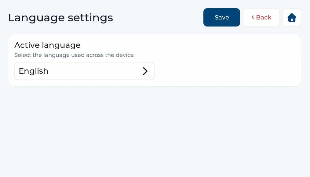
Selecting the active language and saving your choice.
2.3 Checks before the first weighing
Check that the platform is empty and moves freely.
Check the weight display and unit. On a multichannel device, check which platform is selected.
Wait for a stable reading and zero the scale if necessary.
Place a known check load appropriate to the scale's range on the platform and check its response.
If no weight is displayed or the response is incorrect, see Troubleshooting.
Changing the language or connection does not require recalibration. Change scale settings only within your authorisation.
3. Display and controls
3.1 Weight and basic indicators
Field / label | Meaning and use |
|---|---|
Net | Weight of the contents after deducting tare. |
Gross | Total weight of the contents and container. |
Tare | Container weight or the value deducted. Net = gross − tare. |
○ / stability | The circle to the left of the weight display indicates a stable weight. |
No circle | If the circle is absent, the weight is unstable. |
UL / Underload | Underload: the measurement is below the permitted range. |
OL / Overload | Overload: the measurement exceeds the permitted range. Remove the excess load. |
Channel | The selected measuring channel or platform. |
Range | The scale's currently active measuring range. |
3.2 Menus, returning and saving
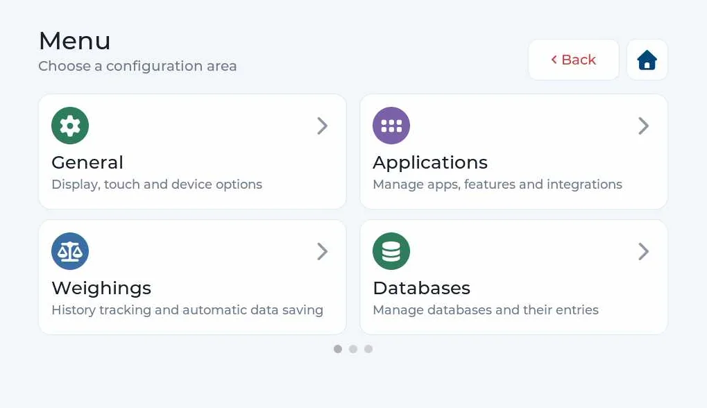
Main menu, page 1: General, Applications, Weighings and Databases.
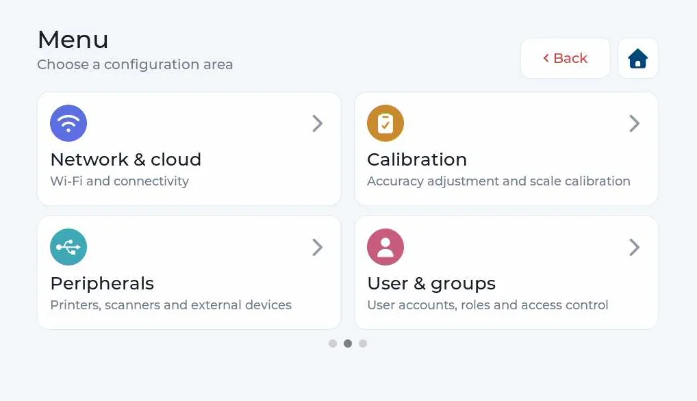
Main menu, page 2: Network & cloud, Calibration, Peripherals and User & groups.
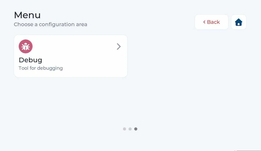
Main menu, page 3: Debug.
3.3 Switching applications
You can quickly switch the active application directly from the main screen.

Example application icon beside the menu button.

The icon may vary with the current application.
- Press the application icon beside Menu in the upper-left corner.
A popup opens with all applications available on the device.
Press the application you want. The device loads it and then displays it.
3.4 Quick menu
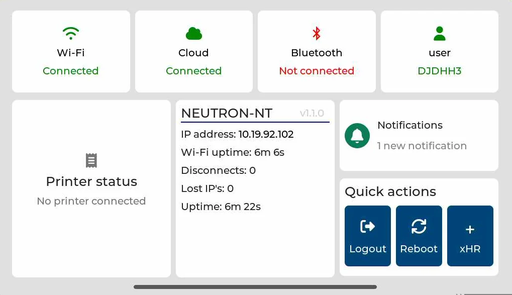
Quick overview of connections, logged-in user and device.
Wi-Fi or Ethernet, cloud and Bluetooth connection status, and the currently logged-in user.
TCP printer connection status.
Basic device information, IP address, uptime and new notifications.
Log out, restart and other shortcuts available on the device.
3.5 Fullscreen display
4. Basic weighing — gross/net
4.1 Main application display
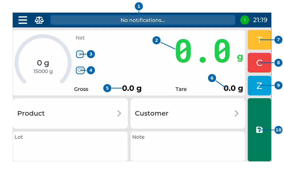
Basic weighing: 1 messages, 2 net weight, 3 stability, 4 scale, 5 gross weight, 6 tare, 7 tare command, 8 clear tare, 9 zero, 10 save.
Label / field | Meaning and use |
|---|---|
1 · Message area | The message area at the top of the screen displays device messages. The illustration shows No notifications…, meaning there are currently no notifications. |
2 · Net — net weight | The large numeric value shows the weight of the contents after tare is deducted. Net = gross − tare. Tap the net-weight field to open the enlarged zoom display. |
3 · ○ — stable weight | A small circle appears to the left of the weight reading, below Net and above the C1 scale label. A visible circle means the weight is stable. No circle means it is unstable. Its position is marked with number 3. |
4 · C1–C4 or R — scale | C1, C2, C3 and C4 identify the scale or weighing channel being displayed. R identifies a reference scale connected via RS-232, RS-485 or TCP/IP. C1 is selected in the illustration. |
5 · Gross — gross weight | Total weight of the container and contents on the scale. Gross = net + tare. |
6 · Tare — tare weight | Container weight or the value deducted from gross weight. Tap the Tare field displaying the tare value to enter tare manually. |
7 · T — tare | Place the empty container on the scale, wait for a stable reading and press T. The current weight becomes the tare, and the net display reads zero. |
8 · C — clear tare | Press C to clear the active tare. When tare is 0, net and gross weights are equal. |
9 · Z — zero | Press Z on an empty scale to zero it. This corrects the empty-scale offset within the permitted range. |
10 · Disk icon — save | Press the disk icon to save the weighing and its associated data. Check the weight, stability and selected data before saving. |
4.2 Entering tare manually
If you already know the container weight, you can enter it directly without weighing the empty container.
- Tap the Tare field displaying the tare value.
Enter the container weight in the correct unit and confirm.
Check the displayed tare and net weight. The entered tare is deducted from gross weight.
- Press C when tare is no longer required.
4.3 Zoom window — enlarged weight display
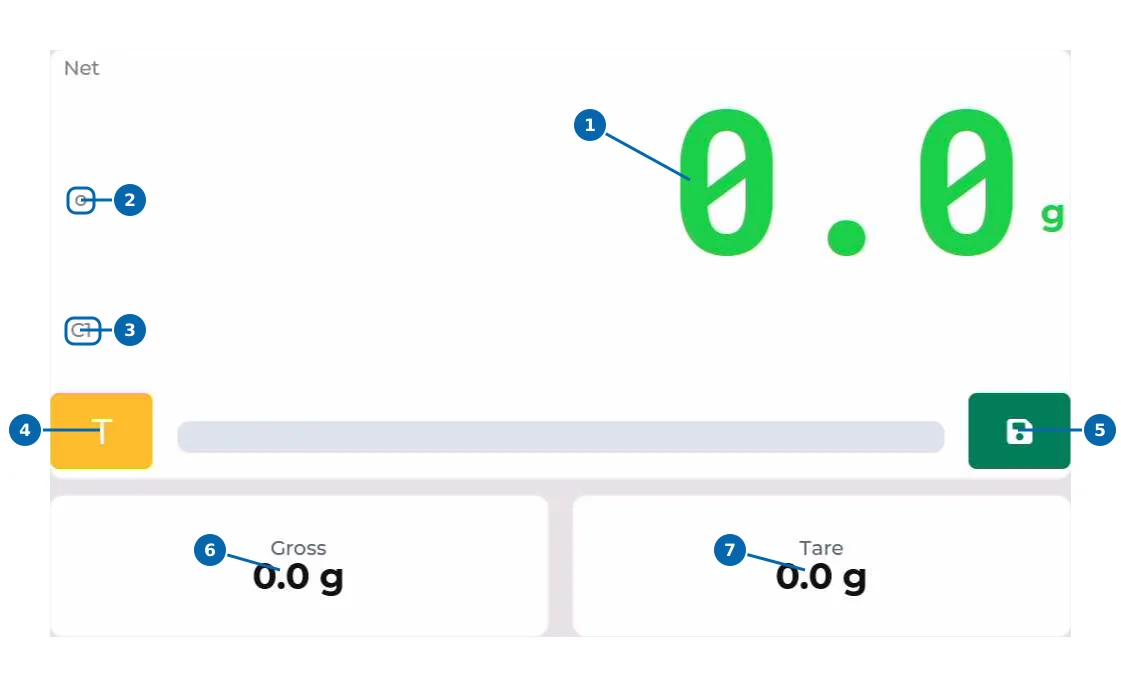
Zoom window: 1 net weight, 2 stability, 3 scale, 4 tare command, 5 save, 6 gross weight, 7 tare.
Label / field | Meaning and use |
|---|---|
1 · Net | Enlarged net weight with unit. |
2 · ○ | The circle on the left of the zoom window indicates a stable weight; if absent, the weight is unstable. |
3 · C1–C4 / R | Label identifying the displayed scale or reference scale. |
4 · T | Tare the current weight. |
5 · Disk icon | Save the weighing. |
6 · Gross | Gross weight. |
7 · Tare | Active tare. |
4.4 Preparing the scale
4.5 Zeroing the scale
Zeroing corrects the empty-scale offset. Use taring to deduct container weight.
4.6 Weighing without a container
Place the load in the centre of the platform without impact.
Wait for a stable reading.
Read the weight and unit. Check that neither OL nor UL is displayed.
If you need a record, save the weighing in the application.
4.7 Weighing with a container: taring
Place the empty container on the unloaded scale.
- Wait for stability and activate T (Tare).
Check that net weight reads zero and the container weight is included as tare.
Add the contents and read the stable net weight.
Save the weighing if your procedure requires a record.
Example: the container weighs 0.500 kg and the contents 2.000 kg. Gross weight is 2.500 kg, tare 0.500 kg and net weight 2.000 kg.
4.8 Saving a weighing
Before saving, select the product, customer and other fields required by your procedure. Save the weighing and check the resulting record. If a stable weight is required, the device will not save the record until that condition is met. See Saved weighings for settings.
4.9 The next weighing
4.10 Example: weighing contents in a container
- The empty scale must be stable and read zero; press Z if necessary.
- Place an empty container weighing 0.350 kg on the platform. Gross weight is 0.350 kg.
- Press T. Tare becomes 0.350 kg and net weight 0.000 kg.
- Add 1.250 kg of contents. Net weight is 1.250 kg, gross weight 1.600 kg and tare remains 0.350 kg.
- Wait for the stability circle and press the disk icon to save.
- Remove the container. If you are not using it again, press C to clear tare and check the empty scale.
5. Weighing with products and customers
- Open Menu and select Databases.
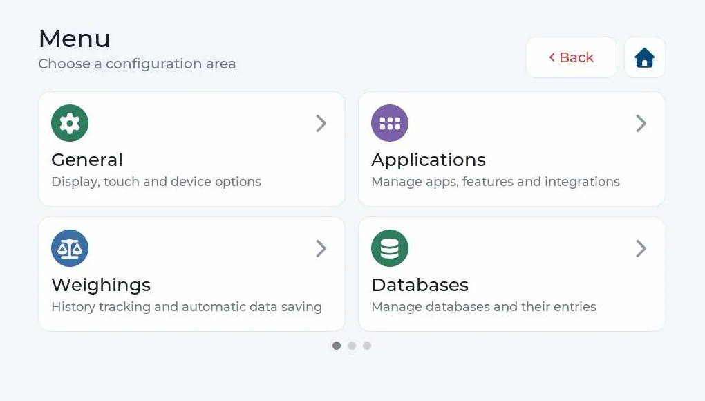
Open Databases from the menu.
All databases installed on Neutron NT are displayed.
- To add an entry, press the green + button beside the relevant database. Select Customer NT for a customer or Product NT for a product.
Enter the required data and save the new entry.
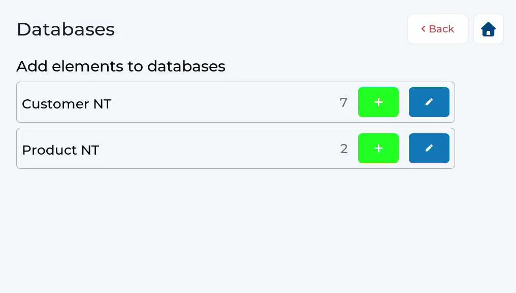
Installed databases; the + button starts adding a new item.
Viewing and editing existing entries
- Press the row of the selected database to open its list of entries.
Press an entry to open its details and edit it.
- Press the star to mark an item as a favourite. Press it again to remove the mark.
When editing an item, you can also configure which details are saved with a weighing and which are displayed when the item is selected in an application.
Selecting a product or customer in an application
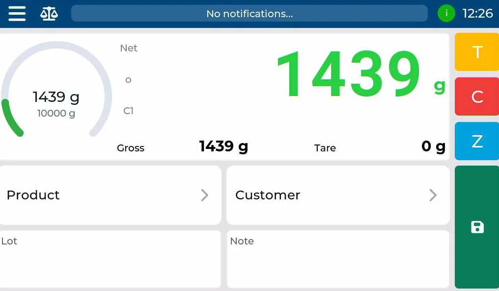
Example application with Product and Customer selection fields.
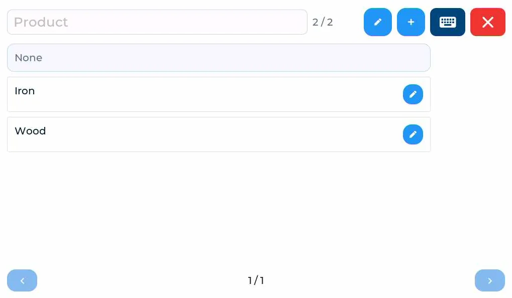
Product list: top pencil for a temporary name, + for a new entry, and the pencil beside a row for editing an existing entry.
5.1 Example workflow
- Press Product in the application and select a product.
- Press Customer and select a customer.
Check the displayed data fields.
Prepare the container, tare it and weigh the contents.
Save the weighing and check that the record is linked to the selected data.
6. Piece counting
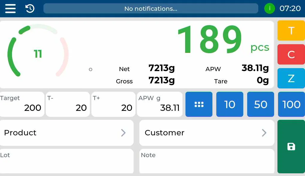
Counting application main screen.
6.1 APW — what does the scale use to count?
Calculated piece count = net weight of all pieces ÷ APW.
The scale does not identify individual pieces. It measures total weight and divides it by APW. Correct tare, a good sample and an appropriate APW therefore directly determine the result. A higher entered APW gives fewer calculated pieces at the same weight; a lower APW gives more.
6.2 How many pieces should a representative sample contain?
Intended quantity | Typical reference sample | Procedure |
|---|---|---|
100 | 10 pieces | Count 10 pieces and select 10. |
250 | 25 pieces | Use 25 actual pieces for the final reference; use the additional piece-count selector. |
500 | 50 pieces | Gradually increase the sample to 50 pieces and confirm it. |
1000 | 100 pieces | Gradually increase the sample to 100 pieces and confirm it. |
10000 | Usually 100 pieces | Check that the batch sample is representative and verify the result using an independently known quantity. |
6.3 Correct procedure: from an initial 10 to 50 or 100 pieces
- Select Counting, check the unit and empty scale. If using a container, place it on the scale and press T.
- Manually count 10 representative pieces, place them in the container and wait for a stable weight.
- Press 10. The terminal calculates the initial APW from these ten pieces.
- For a larger sample, add pieces until the display reads approximately 50 pieces. This uses the scale as a guide when preparing the larger sample, rather than counting all 50 manually at the outset.
- Before confirming, ensure that the sample actually contains 50 pieces. Use an independent check, such as a known number of added pieces, counted groups or previously verified packaging. Then press 50 and observe the APW change.
- If you need a 100-piece reference, add the remaining pieces, verify the actual count, wait for stability and press 100. For another quantity, such as 25, use the additional selector via the dice button.
Use the established APW to count an independently known check quantity. If the result differs, check tare, the sample and differences between batches.
- Then add or remove pieces to reach the required quantity and save the stable result with the disk icon.
6.4 Why can a reference of 1 or 5 pieces cause a large error?
Reference sample | Calculated APW | Actual 100 | Actual 500 | Actual 1,000 | Actual 10,000 |
|---|---|---|---|---|---|
1 piece: a heavier 1.020 g piece is selected | 1.020 g | 98 (−2) | 490 (−10) | 980 (−20) | 9,804 (−196) |
5 pieces: 4 × 1.000 g + 1 × 1.020 g | 1.004 g | 100 (+0) | 498 (−2) | 996 (−4) | 9,960 (−40) |
5 pieces: 3 × 1.000 g + 2 × 1.020 g | 1.008 g | 99 (−1) | 496 (−4) | 992 (−8) | 9,921 (−79) |
5 pieces: 3 × 1.000 g + 1 × 1.020 g + 1 × 0.980 g | 1.000 g | 100 (+0) | 500 (+0) | 1,000 (+0) | 10,000 (+0) |
Two outliers do not necessarily cancel out. If both are heavier, the error increases. In the last row, +0.020 g and −0.020 g cancel in this particular sample, but such a balance is not guaranteed in a small random sample.
6.5 How does a larger sample reduce the effect of one piece?
Assume the reference includes one 1.020 g piece and all others weigh 1.000 g. As normal pieces are added, the same 0.020 g excess is spread over more pieces:
Actual pieces in sample | Net sample weight | Calculated APW | Deviation from 1.000 g/piece |
|---|---|---|---|
1 | 1.020 g | 1.020000 g/piece | +2 % |
5 | 5.020 g | 1.004000 g/piece | +0.4 % |
10 | 10.020 g | 1.002000 g/piece | +0.2 % |
25 | 25.020 g | 1.000800 g/piece | +0.08 % |
50 | 50.020 g | 1.000400 g/piece | +0.04 % |
100 | 100.020 g | 1.000200 g/piece | +0.02 % |
With a correctly established sample of 10 → 50 → 100 pieces, APW in this example changes from 1.002000 to 1.000400 and then 1.000200 g/piece. A rounded screen display may hide small differences. This example demonstrates averaging one outlier; the actual batch may have a different distribution.
6.6 What does an APW error in the third decimal place mean?
Actual quantity at APW 1.000 g/piece | Calculation with APW 1.001 g/piece | Calculation with APW 0.999 g/piece |
|---|---|---|
100 | 99.900 ≈ 100 | 100.100 ≈ 100 |
500 | 499.500 ≈ 500 | 500.501 ≈ 501 |
1000 | 999.001 ≈ 999 | 1001.001 ≈ 1001 |
10000 | 9990.010 ≈ 9990 | 10010.010 ≈ 10010 |
True APW | APW used | Relative APW error | Calculation for 1,000 actual pieces |
|---|---|---|---|
0.100 g | 0.101 g | +1 % | 100.000 ÷ 0.101 ≈ 990 pieces: approximately 10 too few |
1.000 g | 1.001 g | +0.1 % | 1,000.000 ÷ 1.001 ≈ 999 pieces: approximately 1 too few |
10.000 g | 10.001 g | +0.01 % | 10,000.000 ÷ 10.001 ≈ 999.900 pieces: a whole-piece display may still show 1,000 |
6.7 Example: preparing a bag of 250 screws
- Select the screw product and batch, place the empty bag or container on the scale and press T.
- Use 10 actual representative screws for the initial reference and press 10.
- For a final reference when counting 250 pieces, prepare 25 actual pieces. Add 15 verified pieces and use the dice button to enter a reference count of 25.
- Wait for stability and check the new APW. In REL mode set Target = 250; if no deviation in the displayed count is allowed, set T− = 0 and T+ = 0.
Add screws until a stable count of 250 is displayed. Check the product, customer and batch, then save with the disk icon.
Re-establish APW when changing products or batches. For demanding applications, also verify results using an independently known quantity.
Zero tolerances require the calculated count to match the target. They do not eliminate APW error or themselves guarantee that the actual quantity has no deviation.
6.8 Application settings and fields
Field | Meaning |
|---|---|
Target | Target piece count. |
T− / T+ | Permitted deviation below or above the target. |
ABS — Absolute | Directly specified lower and upper limits for an acceptable piece count. |
REL — Relative | Target piece count and permitted deviations. |
Counting decimals | Number of decimal places in the displayed piece count. |
APW decimals | Number of decimal places in the APW display. This setting does not itself improve sampling. |
APW / PMK | Average piece weight. Tap the field to change its value. |
10 / 50 / 100 | Confirm the actual number of reference pieces on the scale with the button. The device calculates APW from their weight. |
Dice button | Additional reference-count selection or direct APW entry. |
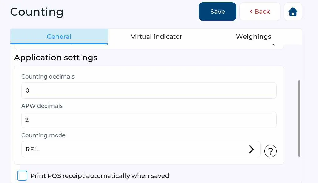
Counting, General tab: count and average-piece-weight decimals, and counting mode.
6.9 Default zoom indicator
The default Counting zoom indicator emphasises the piece count. Alongside the enlarged result, it shows weights, tare, target, tolerances and APW — average piece weight.
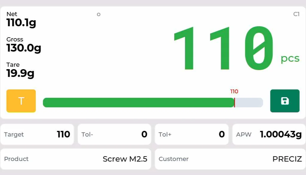
Piece counting: enlarged count, weight, tare, target, tolerances and average piece weight (APW).
In the example, the result is 110 pcs, Target is 110, Tol− and Tol+ are 0, and APW is 1.00043 g/piece. On the left are net weight 110.1 g, gross weight 130.0 g and tare 19.9 g. The selected product and customer appear below.
The circle indicates stable weight; if absent, weight is unstable. C1 identifies the displayed scale. T tares the scale; the disk icon saves the weighing.
7. Checkweighing
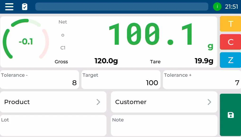
Checkweighing in Relative mode: target 100 g, lower deviation 8 g, upper deviation 7 g and current net weight 100.1 g.
The upper card shows net weight, gross weight, tare and a graphical deviation indicator.
- Press Low, Target or High to enter the corresponding value where the selected mode permits it.
- In Absolute mode, Target is greyed out or disabled; the lower and upper limits are used.
Settings → Applications → Checkweighing. In Relative mode, set Target and tolerances T− and T+; in Absolute mode, set Low and High.7.1 Modes and parameters
Field / label | Meaning and use |
|---|---|
Low / lower limit | Lowest permitted weight in ABS mode. |
High / upper limit | Highest permitted weight in ABS mode. |
Target | Target net weight in REL and PER modes. |
T− / T+ | Permitted deviation below or above the target. |
ABS — Absolute | Enter the lower and upper limits in weight units. |
REL — Relative | Enter the target weight and deviations in weight units. |
PER — Percent | Enter the target weight and deviations as percentages of the target. |
7.2 Checkweighing procedure
- Select Checkweighing.
Select ABS, REL or PER in the application settings and save the change.
Set the limits or target and deviations in the application.
Tare the container if one is used.
Place the product on the scale and wait for a stable reading.
Read the weight and graphical deviation indicator, then save the weighing if required.
7.3 Checkweighing-specific settings
7.4 Example: filling to 1 kg
Stable net weight | Result for the 0.990–1.010 kg range | What to do |
|---|---|---|
0.985 kg | Underweight | Add contents and recheck the stable result. |
1.004 kg | Acceptable weight | Save the weighing and prepare the next container. |
1.018 kg | Overweight | Remove contents and recheck the stable result. |
Check tare before the next container. If empty-container weights vary, tare each appropriate empty container again; incorrect tare directly changes the net-weight check result.
This chapter describes the static Checkweighing application. The automatic Checkweigher application for conveyor weighing has separate procedures and parameters.
7.5 Default zoom indicator
The default Checkweighing zoom indicator shows an enlarged net weight and a graphical indication relative to the target and permitted deviations.
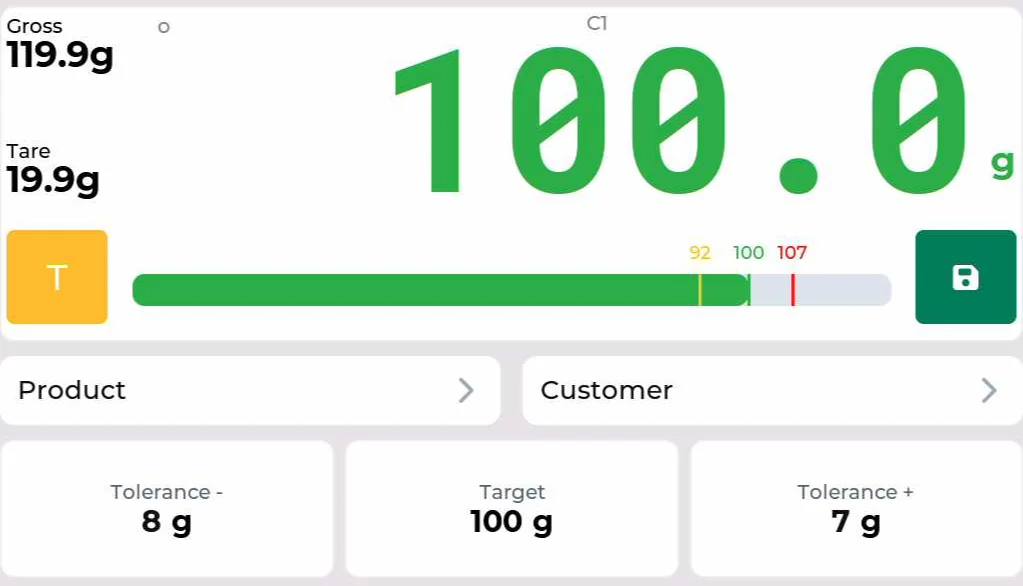
Checkweighing: enlarged net weight, gross weight, tare, target and permitted deviations.
In the example, net weight is 100.0 g, gross weight 119.9 g and tare 19.9 g. Target is 100 g, Tolerance − is 8 g and Tolerance + is 7 g. The acceptable range is therefore 92 to 107 g; the current weight is shown in green.
The circle indicates stable weight; if absent, weight is unstable. C1 identifies the displayed scale. T tares the scale; the disk icon saves the weighing.
8. Saved weighings and automatic saving
8.1 Viewing a record
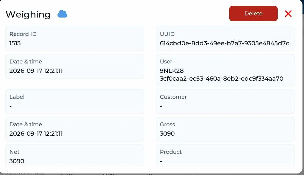
A cloud icon beside a weighing means the record was successfully sent to the cloud; its Record ID is shown below.
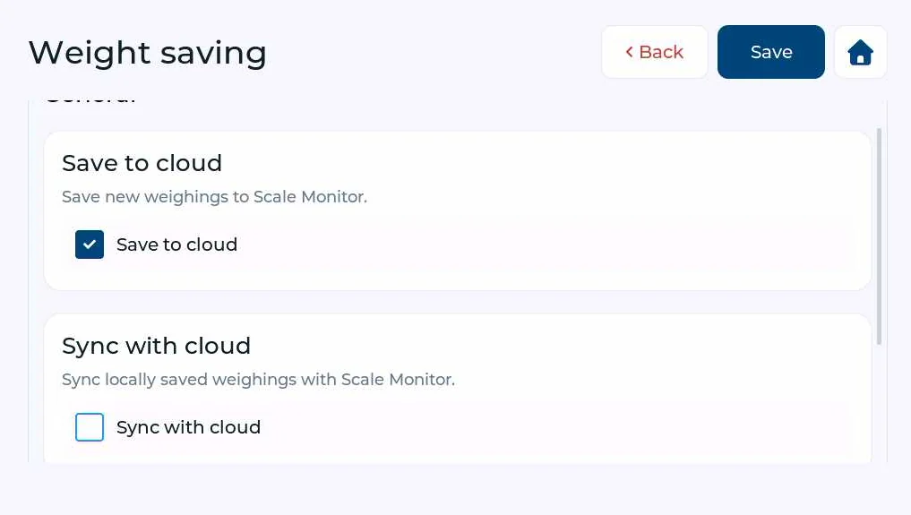
Weight saving: Save to cloud and Sync with cloud options, and Save button.
8.2 Saving settings for each application
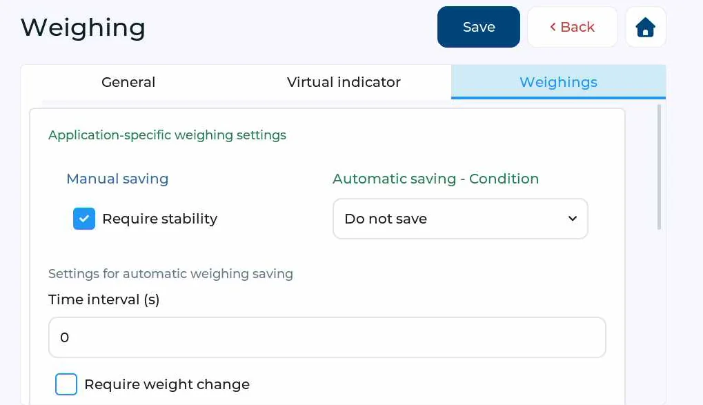
Weighings: stability for manual saving, automatic-saving mode and time interval.
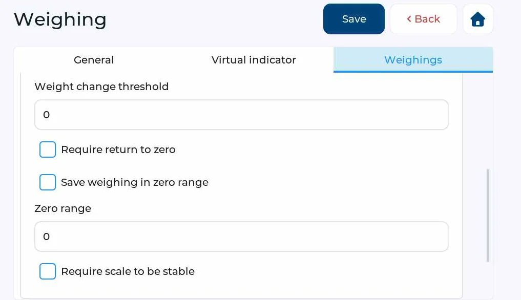
Weighings: weight-change threshold and return-to-zero options.
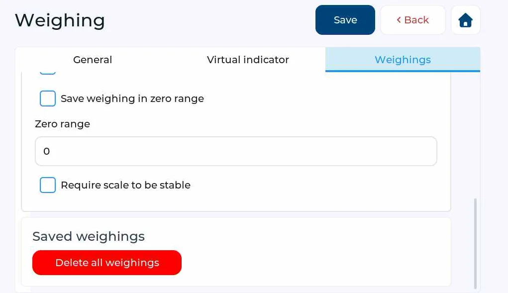
Weighings: zero range, stability and the button for deleting saved weighings.
8.3 Meaning of saving conditions
Field / label | Meaning and use |
|---|---|
Manual saving | Conditions for manual saving, especially the stability requirement. |
Automatic saving – Condition | Mode selection: disabled, time intervals or individual weighings. |
Time interval | Time between records in seconds for interval saving. |
Require weight change | The weight must change by the configured threshold before a new record is saved. |
Require return to zero | The scale must return to the zero range before the next automatic record. |
Save weighing in zero range | Also permit saving within the configured zero range. |
Zero range | Width of the range that the saving function treats as zero. |
Stability | If enabled, saving is permitted only when the weight is stable. |
8.4 Example: one record for each loaded container
Select individual-weighing saving and require stability and return to zero. Place a loaded container on the scale, wait for the record and remove it. Before the next container, wait until the return-to-zero condition is met. Test these settings with your taring procedure.
The saving zero range and the range permitting a zeroing command serve different purposes. The first controls record triggering; the second is a scale setting under Calibration.
9. Network connection and Scale Monitor
9.1 Wi-Fi
- On the main screen, open Menu using the upper-left button.
- Swipe through the menu pages to Network & cloud and open it.
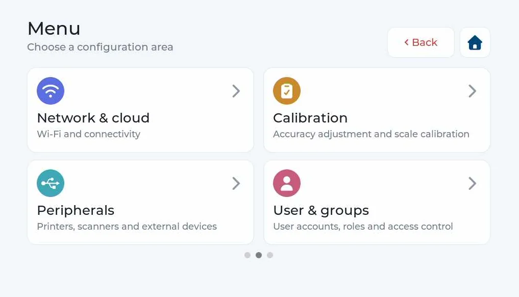
Select Network & cloud from the menu.
- Under Internet interface, select the connection type. Wi-Fi is selected by default; Ethernet or LTE can also be selected if the appropriate module is installed.
- Open the Wi-Fi card.
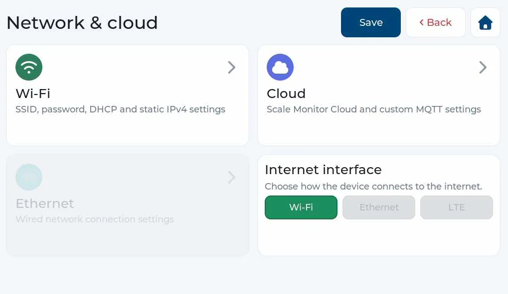
Selecting the internet interface and opening Wi-Fi settings.
- Press Scan networks to search automatically, then select your network. You can also enter its details manually.
Enter the network name (SSID) and password.
- For IP settings, leaving DHCP enabled is usually simplest.
- Press Save and wait for the device to connect.
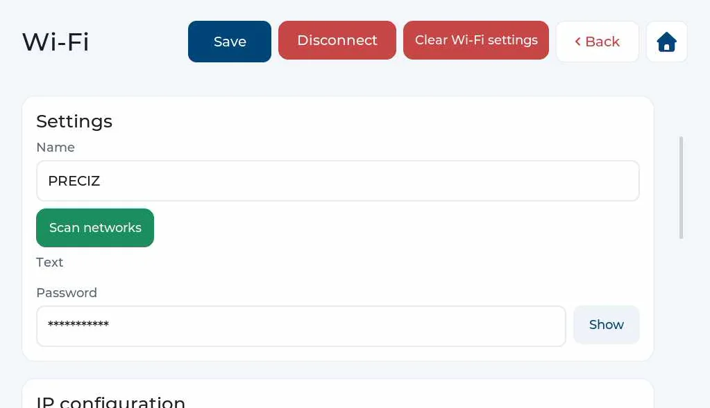
Search for a network or enter its details manually.
9.2 Ethernet
If an Ethernet module is installed, select it as the internet interface and connect the device with a network cable. Configure the connection type and network details for your network, then save the changes.
9.3 Network fields explained
Field / label | Meaning and use |
|---|---|
SSID | Wireless network name. |
DHCP | Automatic assignment of an IP address and other network settings. |
IP address | Device address on the network. For a static address, use the details supplied by your administrator. |
Gateway | Network gateway to other networks or the internet. |
DNS | Service that resolves server names to IP addresses. |
NTP | Network synchronisation of date and time. |
MID | Module ID: unique module identifier. |
PIN | Module access credential. Keep it confidential. |
9.4 Cloud connection
9.5 Sending and synchronising weighings
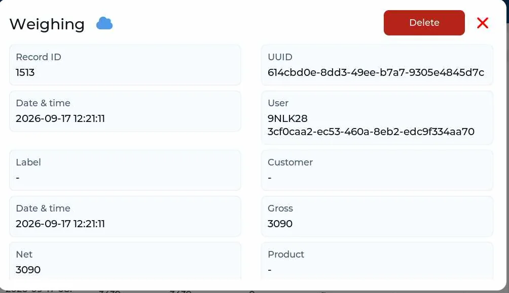
A cloud icon beside a weighing means the record was successfully sent to the cloud; its Record ID is shown below.
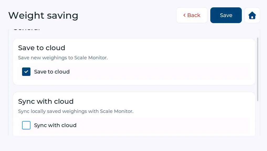
Weight saving: Save to cloud and Sync with cloud options, and Save button.
9.6 Checking operation
In the quick menu, check the Wi-Fi or Ethernet connection and cloud status.
Save a test weighing.
Check for the cloud icon beside the record.
- If older records are still unsent, use Weighings → Weight saving → Sync with cloud → Save.
10. Printing and accessories
10.1 Connecting a printer
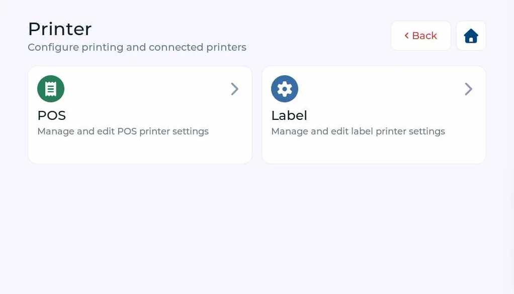
Printer menu with POS or Label selection.
Field / label | Meaning and use |
|---|---|
RS-232 | Serial connection. Baud rate, data bits and parity must match the printer. |
TCP/IP | Network connection. Enter the printer's IP address and port. |
Baud rate / bps | Serial transmission speed in bits per second. |
Parity | Transmission checking: none, even or odd parity. |
Port | Printer network-service port number. |
10.2 Printing a weighing slip — thermal printer (POS)
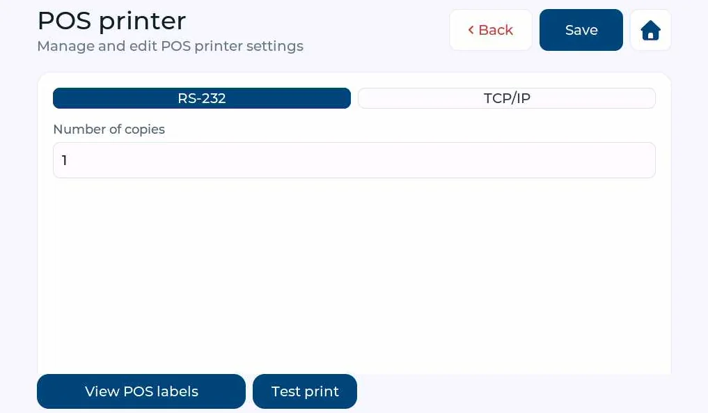
POS printer: RS-232 tab and template-viewing button.
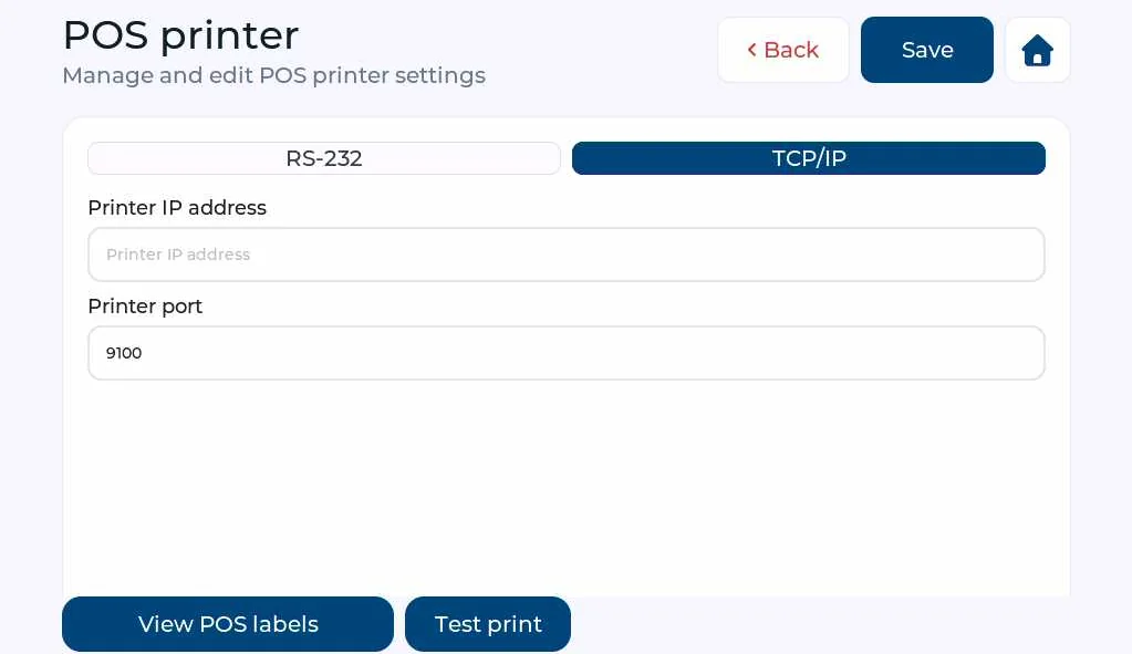
POS printer: TCP/IP tab with IP address and port.
10.3 Label printing and templates
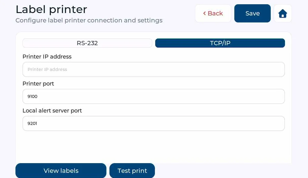
Label printer: TCP/IP settings, alert port, View labels and Test print buttons.
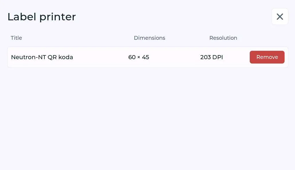
Installed label templates with size and resolution information.
Field / label | Meaning and use |
|---|---|
ZPL — Zebra Programming Language | Template language defining label content and layout. The printer must support the language used. |
View labels | View label templates transferred to the device. |
Test print | Test output using the configured printer. |
Local alert server port | Local network port for printer alerts; connection settings must match the equipment used. |
10.4 Automatic printing and photography when saving
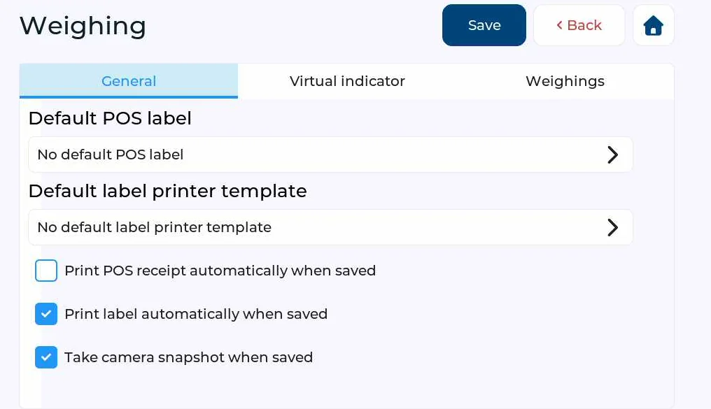
Weighing, General tab: print templates and automatic actions when saving.
10.5 Camera
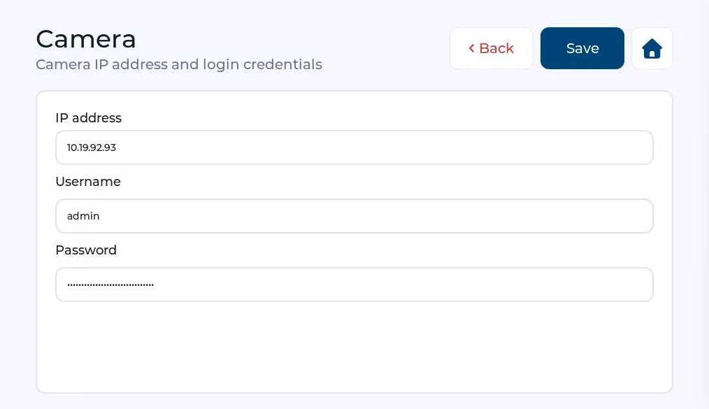
Camera settings: IP address, username and password.
10.6 Communication interfaces and digital I/O
Serial and network interfaces connect the terminal to other equipment. The datasheet lists Modbus RTU, Modbus TCP, TCP/IP, REST, MQTT/MQTTS and WebSocket/WSS. Modbus connects to PLCs or supervisory systems; REST exchanges data over HTTP/HTTPS. MQTTS and WSS use TLS-protected transport.
Digital inputs can trigger zeroing, taring or other configured functions. Outputs can indicate tolerance status or control suitable process functions. An integrator should configure connection assignments and functions.
Field / label | Meaning and use |
|---|---|
I/O — Input/Output | Digital inputs and outputs. |
Digital inputs | 6 optically isolated inputs; 10–24 V DC ±5 %, current 4–35 mA according to the datasheet. |
Digital outputs | 6 PhotoMOS outputs; 5–24 V DC, maximum 150 mA. |
PLC | Programmable logic controller for automation. |
TLS | Protection of data in transit over a network. |
UART / RS-232 / RS-485 | Different electrical interfaces for serial communication; connection requires appropriate signal levels and wiring. |
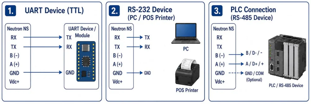
Examples of UART, RS-232 and RS-485 serial connections.
The Vdc+ supply terminal in the illustrated low-voltage diagram is not the terminal's mains connection. Never connect 230 V mains to communication or I/O terminals.
11. Customising the device and applications
11.1 Language
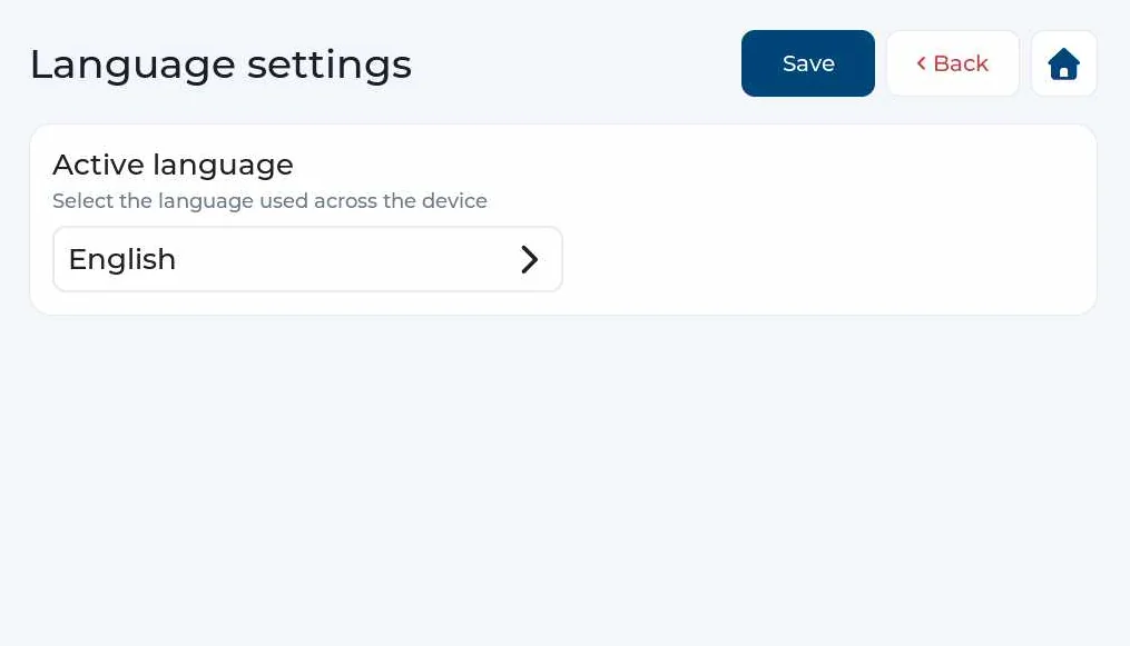
Selecting the active language and saving your choice.
11.2 Date and time
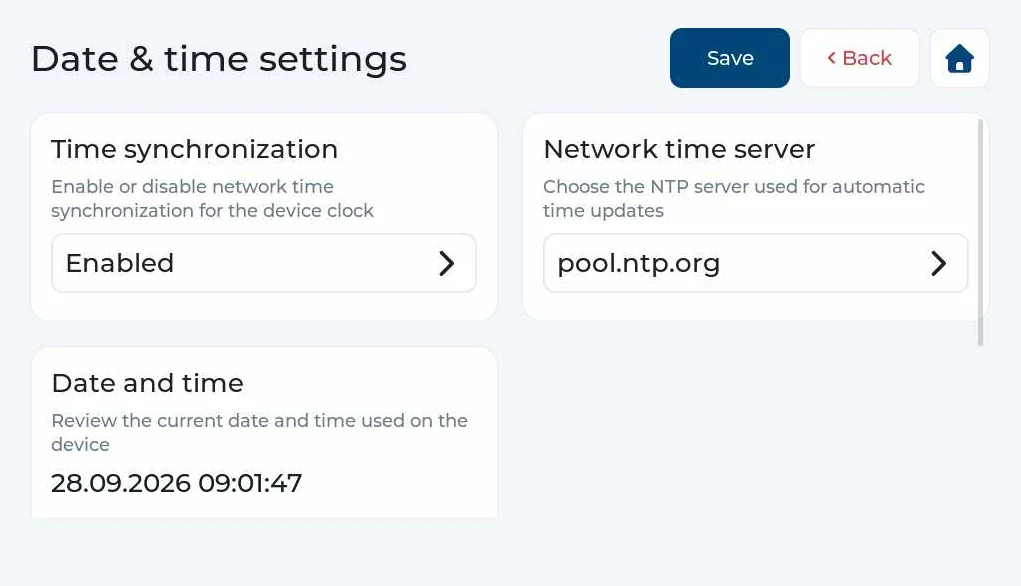
Date and time: synchronisation, NTP server and current time.
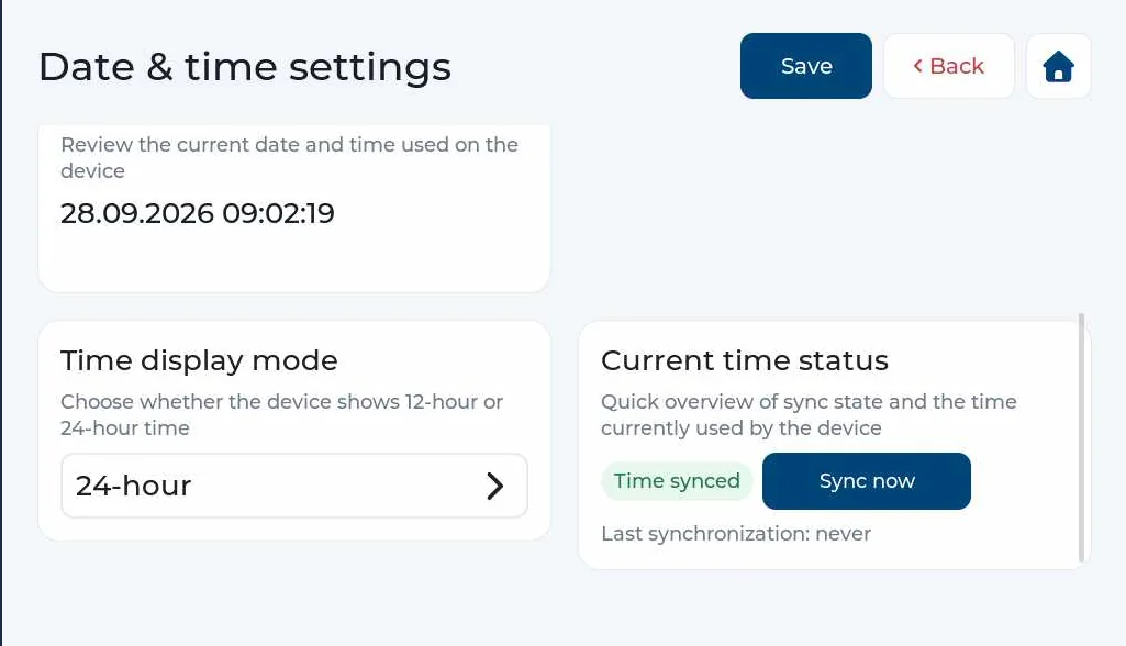
Date and time: display mode and manual synchronisation.
11.3 Display
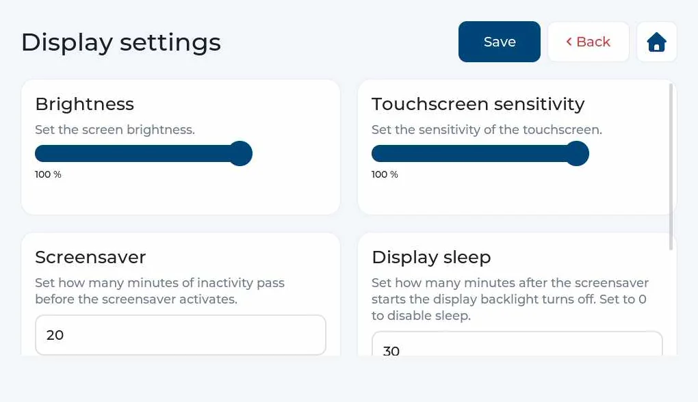
Display: brightness, touch sensitivity and screensaver delay.
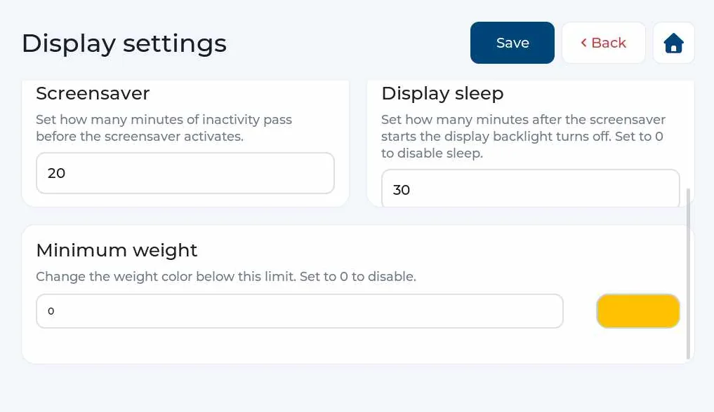
Display: backlight-off delay, minimum weight and colour indication.
11.4 Device name
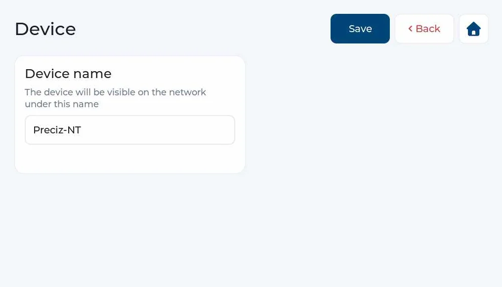
Device: network device-name field.
11.5 Selecting a display and fullscreen mode
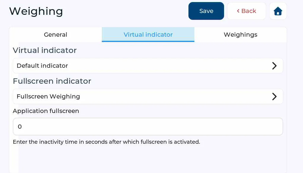
Weighing, Virtual indicator tab: standard and fullscreen displays and automatic-opening delay.
Field / label | Meaning and use |
|---|---|
Virtual indicator | Weighing-display template for each application. |
Application fullscreen | Inactivity time in seconds before automatic fullscreen display. |
Application fullscreen = 0 | Automatic switching is disabled. Tap the weight to open fullscreen mode. |
12. Users, permissions and traceability
12.1 Users
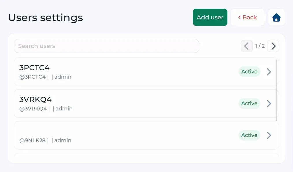
User list with Add user and access to individual entries.
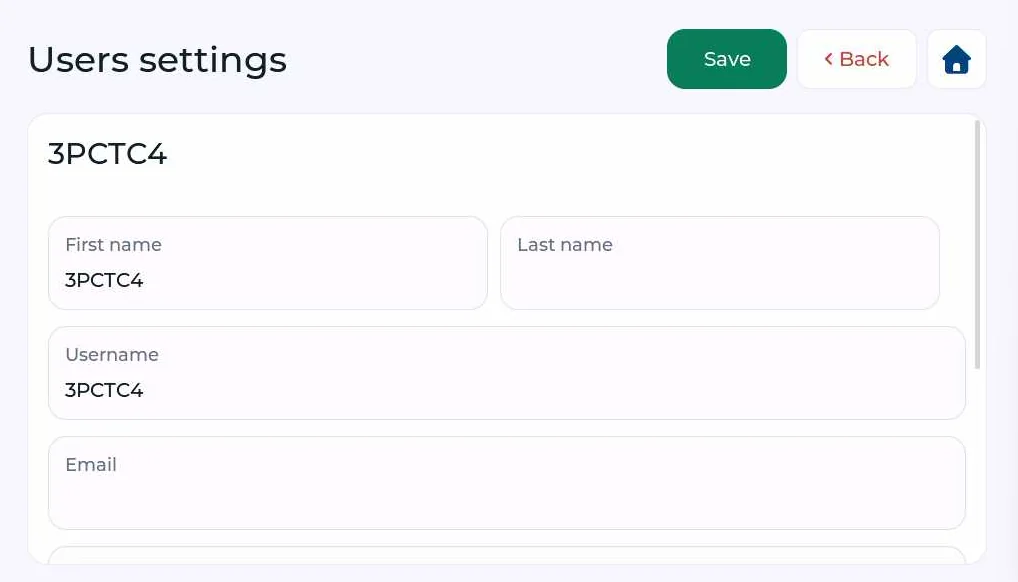
Editing the selected user's details.
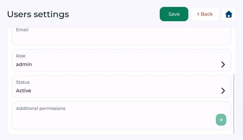
Editing group and status, and opening additional user permissions.
12.2 Groups
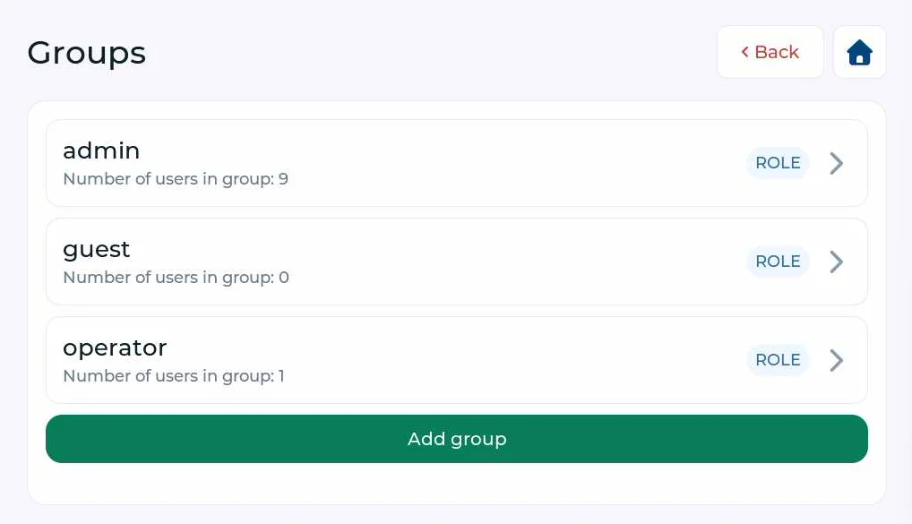
Group list and Add group button.
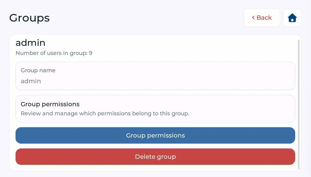
Editing a group with Group permissions and Delete group options.
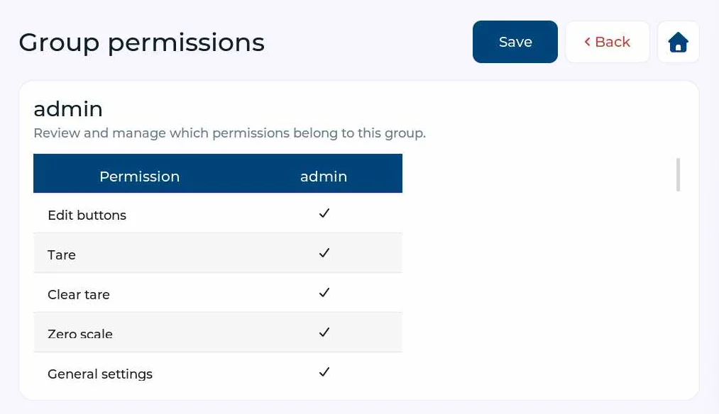
Group-permissions table; ticks indicate assigned permissions.
12.3 Additional permissions
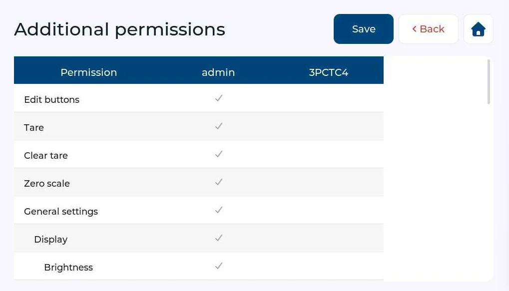
Additional-permissions table: group and selected-user columns.
12.4 Login and session duration
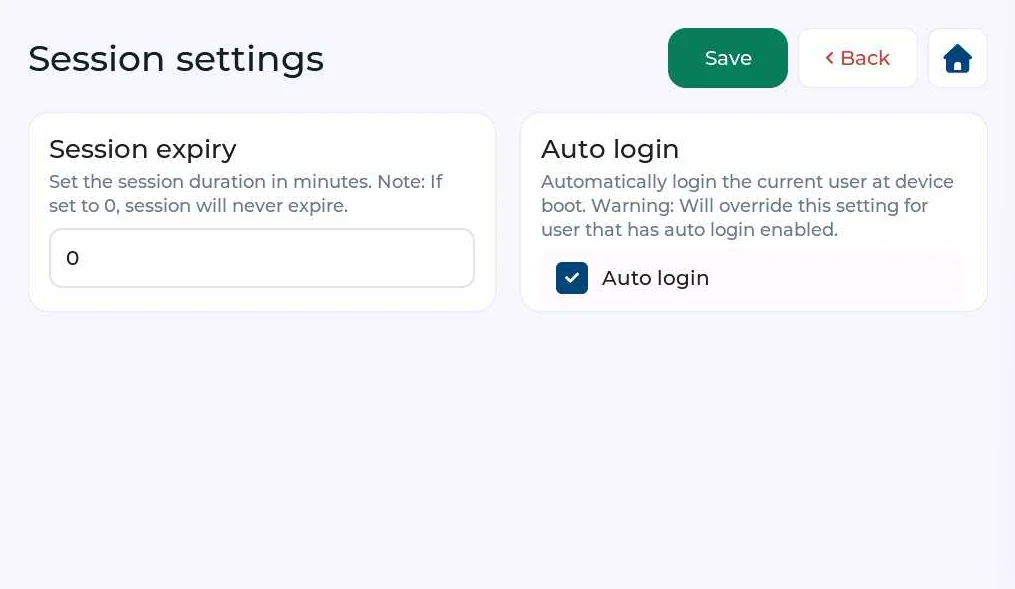
User session-expiry and automatic-login settings.
12.5 Audit log
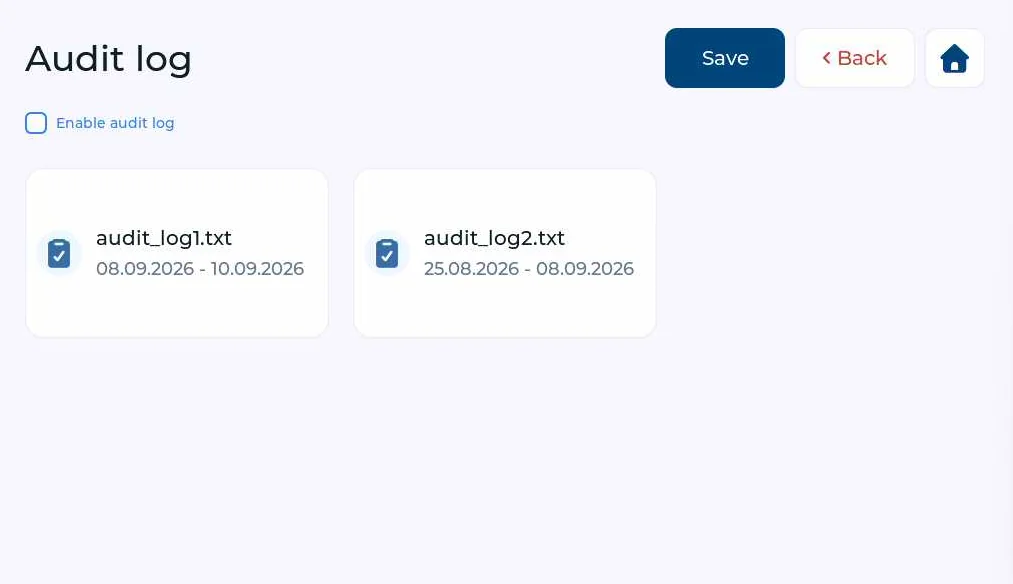
Enabling logging and viewing saved log files.
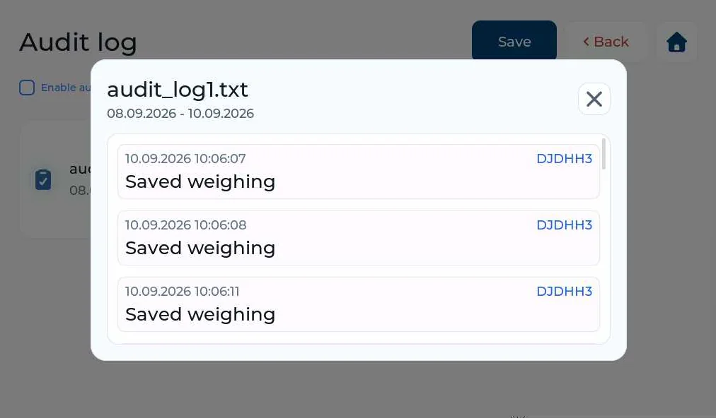
Example event view in a selected log file.
Field / label | Meaning and use |
|---|---|
Audit log | Log of recorded user actions. |
Session expiry | Session duration in minutes; 0 means no automatic expiry. |
Auto login | Automatic login of the selected user at startup. |
Group permissions | Permissions inherited by group members. |
Additional permissions | Additional permissions assigned to an individual user. |
13. Maintenance, backups and updates
13.1 Cleaning and regular inspection
Disconnect power before cleaning. Use a soft cloth and a cleaner suitable for stainless steel, the display and seals. Avoid mechanical damage to the screen, cable glands and cables. Before reuse, check connections for damage and tightness. IP67 alone does not establish resistance to cleaning chemicals or high-pressure washing.
13.2 Storage and settings backup
View internal-storage and SD-card usage. Buttons are available to back up settings and restore them from a previously created backup.
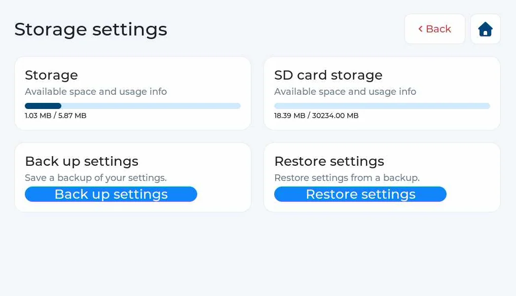
Storage: available space and settings backup and restore buttons.
Back up settings before major changes. Restore only to an appropriate device and configuration. A settings backup is not an archive of all weighings and logs.
13.3 Software updates
The device can check whether a newer software or firmware version is available.
- Open Menu → General.
- Swipe to the second page and open Update.
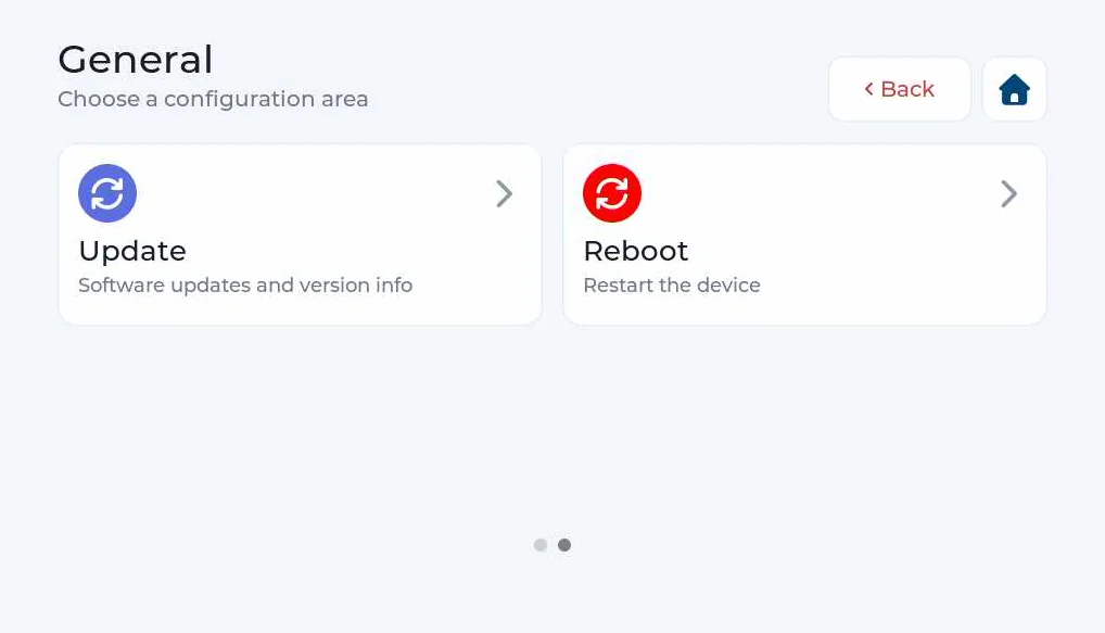
Select Update on the second General page.
- On the Update screen, press Check for updates.
- If a new version is available, an Update to version … button appears. Press it to start the update.
If no update is available, the device reports that the latest version is already installed.
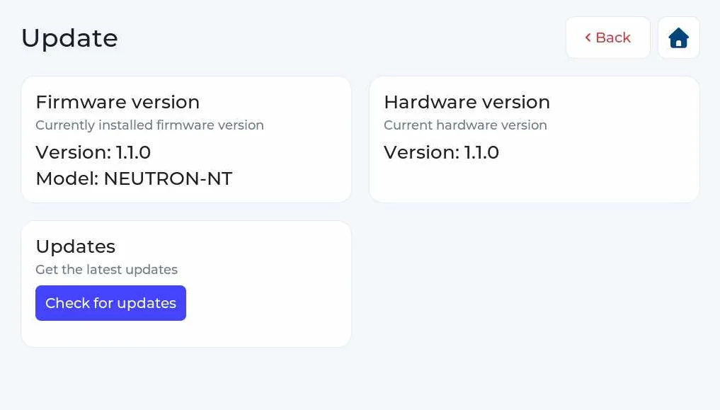
Select Check for updates first.
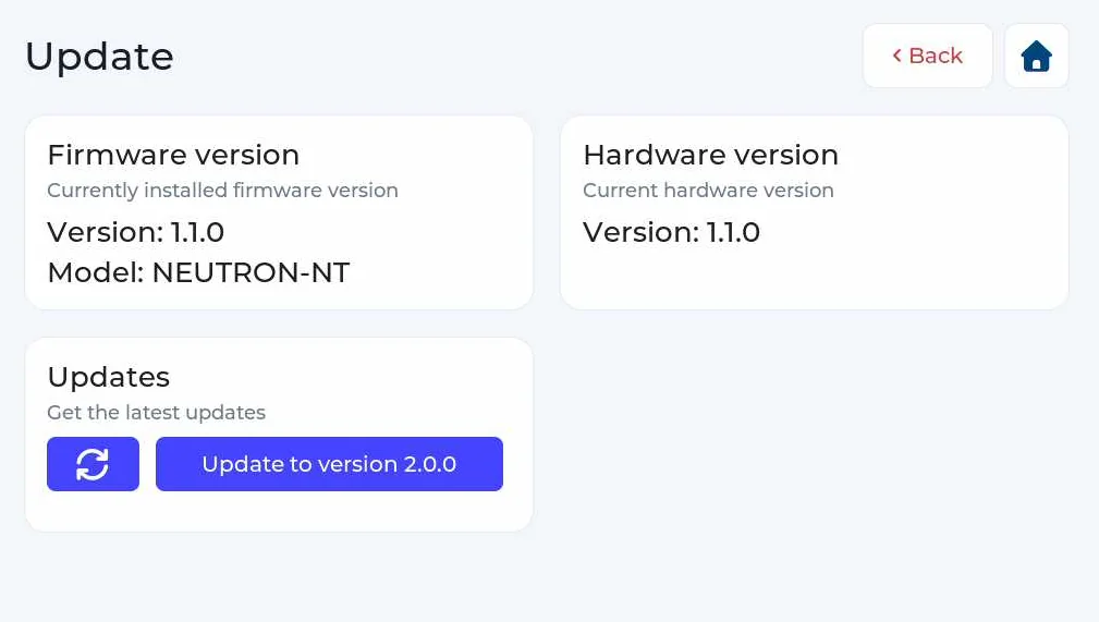
When an update is available, select Update to version …
13.4 Restarting
14. Troubleshooting and support
Problem / indication | What to do |
|---|---|
No weight displayed | Check power, the scale connection, selected channel and measuring-signal status. Contact support if the problem persists. |
Unstable weight | Check for vibration, draughts, platform contact and cable tension. An authorised person should adjust filtering and stability settings. |
Zeroing fails | Empty the platform, wait for stability and check active tare. The command may be limited by the zeroing range or timeout. |
Negative weight after removing the container | Check active tare. Use Clear tare if the container is no longer in use. |
OL / UL | Check loading and correct positioning. For OL, remove the excess load. If the indication remains on an empty platform, contact service. |
Cannot save a weighing | Check user permissions, required data fields, stability and available storage. |
Automatic records repeat or are missing | Check the time interval, required weight change, return to zero and permission to save in the zero range. |
Wi-Fi does not work | Check the 2.4 GHz network, SSID, password, signal and DHCP. For an Enterprise network, verify credentials with your administrator. |
No cloud connection | Check the local network, internet access and cloud connection separately in the quick menu. |
Weighings are not in the cloud | Check the Scale Monitor plan, Save to cloud and the cloud icon. For pending records, use Sync with cloud and Save. |
Printer does not print | Check power, paper or labels, the RS-232 or TCP/IP connection, communication settings and template. Run Test print. |
Camera does not capture an image | Check the camera's IP address, username and password, and that photography is enabled in the application settings. |
Function unavailable | Check user permissions and the available application configuration. |
Calibration ends with CE | Remove vibration, check that loads increase between points and repeat the point with a stable signal. |
14.1 Information for support
Prepare the device model and identification, software version, connected-platform description, selected application, exact error message and the steps that trigger the problem. Include a screen photograph if needed. Share PINs and passwords only through an agreed secure channel.
15. Scale settings and calibration
This chapter is for personnel authorised to configure the scale. Changes to measuring ranges, scale intervals and calibration points affect weighing results. Save settings and prepare suitable reference loads before making changes.
15.1 Opening calibration and checking the signal
Field / label | Meaning and use |
|---|---|
ADC — Analog-to-Digital Converter | Analog-to-digital converter. ADC value is the raw numeric load-cell signal. |
mV — millivolt | Unit of electrical voltage. The displayed value is the load-cell signal. |
Channel | Measuring channel. Changing the channel loads its settings. |
Range | Active measuring range. |
ADC min / max | Minimum and maximum detected ADC values, useful for assessing signal fluctuation. |
= / ~ / UL / OL | Stable weight / unstable weight / underload / overload. |
15.2 Metrological settings
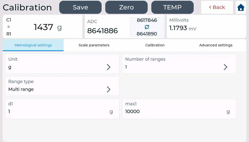
Metrological settings tab: channel, measurement status, weight, ADC values, mV signal and range settings.
Field / label | Meaning and use |
|---|---|
Unit | Display unit, such as kg, g or t. Enter load values in the appropriate unit. |
Number of ranges | Number of measuring ranges: 1 to 3. |
Range type | Operating mode of the scale intervals or measuring ranges. |
d1, d2, d3 | Display interval for each range: the smallest displayed weight increment. |
Max1, Max2, Max3 | Maximum weight of each measuring range. |
Example: Max1 = 60 kg, d1 = 0.01 kg | The display changes in 10 g increments. Entering a smaller increment does not itself improve the measuring capability of the load cells and platform. |
15.3 Scale parameters
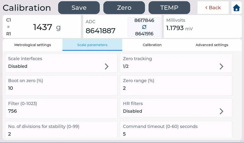
Scale parameters tab with zero, filter, stability and communication settings.
Field / label | Meaning and use |
|---|---|
Scale interface | Communication interface for connecting the scale. |
Zero tracking | Automatic tracking of small zero offsets. The range is expressed in scale intervals; options are Disabled, 1/4, 1/2, 1, 2, 4, 8 or 10 intervals. |
Boot on zero | Proportion of maximum capacity within which automatic startup zeroing is permitted. |
Zero range | Permitted range for the zeroing command, expressed as a percentage of maximum capacity. |
Filter | Digital signal filtering. Higher values steady the display and slow the response. A value of 0 disables this filter. |
HR filter – High Resolution | Additional high-resolution filtering; reduces noise and increases settling time. |
Number of divisions for stability | Permitted fluctuation in scale intervals for stability detection. At 0, weight is always treated as stable. |
Command timeout | Maximum wait for command execution. If the weight does not settle in time for taring, the command is cancelled. |
15.4 Preparing to capture calibration points
Check mechanical positioning, correct load-cell connections and the selected channel.
Check the unit, capacity and scale interval, and prepare reference loads of known weight.
Remove all loads from the platform and prevent vibration.
- Open the Calibration tab.
15.5 Zero point and loaded points
- Empty the scale and press Calibrate at point 0. After a few seconds, the measured value appears in the ADC column.
- Place a known load on the scale. At point 1, enter its weight in Mass and press Calibrate. An ADC value is recorded for this point too.
- If additional calibration points are needed, repeat using suitable known loads. Finally, press Save to send the data to the scale.
The same tab provides options to delete an individual calibration point or all points. Check carefully which points you are removing.
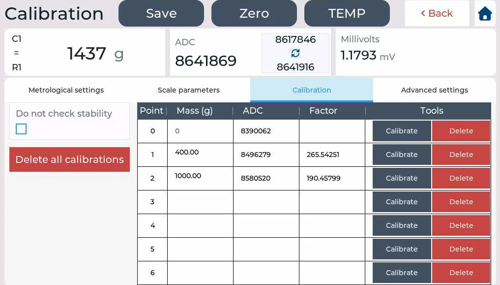
Calibration tab: points 0, 1 and subsequent points, with Mass and ADC columns and Calibrate buttons.
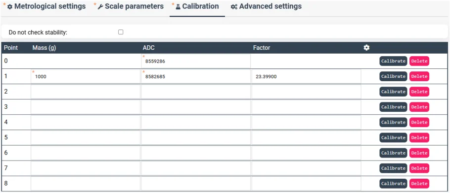
Capturing calibration points: reference weight, ADC value and Calibrate command.
15.6 Calibration messages
Field / label | Meaning and use |
|---|---|
CS | Calibration starts. |
C1–C10 | Sequence of attempts while waiting for a stable signal. |
CF | Calibration point captured successfully. |
CE | Calibration error. Check stability, the load and point sequence. |
Point / Mass / Factor | Calibration-point number / reference weight / calibration factor converting signal to weight. |
Do not check stability | Disables stability checking when capturing a point. An unstable signal may cause an unreliable adjustment, so this is not a normal way to resolve an error. |
If the signal is still unstable after ten attempts, calibration ends with CE. Improve the conditions first and repeat the point. Manual entry of ADC values and calibration factors is intended for expert adjustment.
15.7 Advanced settings and stability window
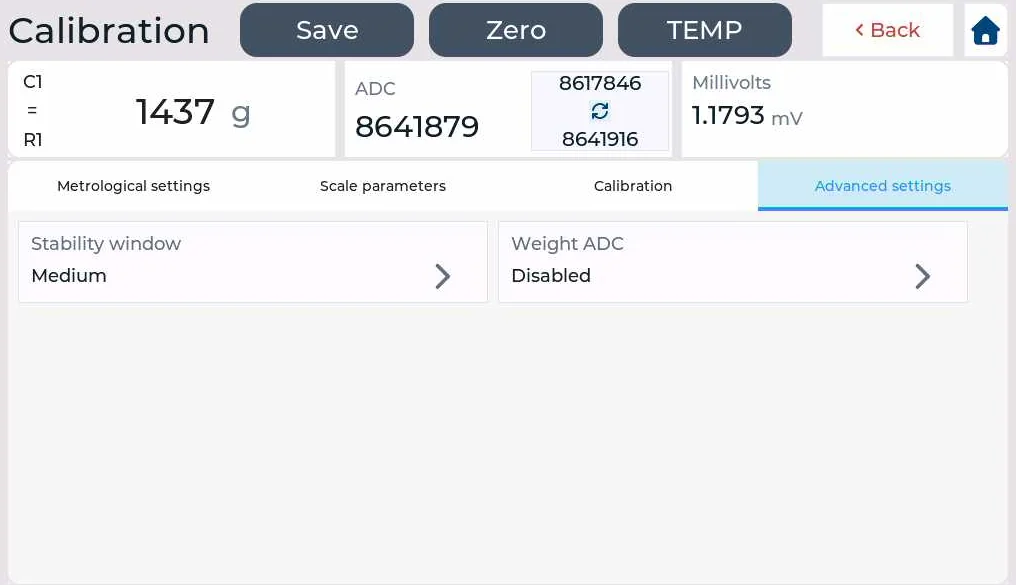
Advanced settings tab with Stability window and Weight ADC.
Field / label | Meaning and use |
|---|---|
Stability window | Additional time for which the measurement must remain stable before the device confirms stability. |
Quick | 0.25 s; if the weight changes during this time, stability is not confirmed. |
Medium | 0.5 s; the default selection in the Neutron family manual. |
Slow | 1 s; longer stability verification. |
Wait ADC / Weight ADC | Manufacturer's advanced parameter. Leave it disabled during normal operation. |
For high resolution, the manual recommends Medium or Slow. Quick is suitable for standard resolution up to 10,000 intervals in a stable environment.

Advanced settings: stability-window selection and Wait ADC parameter.
15.8 Saving and checking the result
- Press Save to send settings to the scale.
Remove the load and check the zero reading.
Check readings using several known loads within the operating range.
Repeat loading and unloading to check repeatability.
Before returning to operation, also check taring, saving and process limits if used.
16. Quick reference: menus and terms
Menu | What you configure |
|---|---|
General | Language, date and time, display, storage, update, name and restart. |
Applications | Individual application, display and automatic-action settings. |
Weighings → Weight saving | Sending and synchronising weighings to the cloud. |
Databases | Databases for products, customers and other installed collections. |
Network & cloud | Network interface and cloud connection. |
Calibration | Measuring channel, measuring ranges, parameters and calibration points. |
Peripherals | Printers, camera and other connected equipment. |
User & groups | Users, groups, permissions, log and session. |
Debug | Diagnostics for service and integration. |
16.1 Abbreviations
Field / label | Meaning and use |
|---|---|
APW / PMK | Average Piece Weight: reference-sample weight divided by its actual number of pieces. The Slovenian abbreviation is PMK. |
ABS / REL / PER | Absolute limits / relative deviations / percentage deviations. |
ADC / mV | Raw converter value / electrical signal in millivolts. |
POS / ZPL | Thermal-printer output settings / label-printer template language. |
DHCP / DNS / NTP | Automatic network configuration / name resolution / time synchronisation. |
MID / PIN | Module identifier / module access credential. |
BLE | Bluetooth Low Energy, a wireless communication interface. |
ERP / MES / WMS | Enterprise resource planning / manufacturing execution system / warehouse management system. |
16.2 Related documentation
Frequently asked questions
How do I zero the scale?
Empty the platform, wait for stability and activate Zero. Use Tare for container weight.
What is APW?
APW is the average weight of one piece. Counting uses it to convert net weight into a piece count.
What does the cloud icon beside a weighing mean?
The record was successfully sent to the cloud. For pending records, use Sync with cloud under Weighings → Weight saving.
How do I enable printing when saving?
Configure the printer first and run Test print. Then select a template under General in the chosen application and enable automatic printing.
What does calibration error CE mean?
Calibration failed. Check stability, the appropriate load and an increasing sequence of points, then repeat the capture.
Can several users have automatic login enabled?
Automatic login can be enabled for only one user at a time. Enabling it for another user disables it for the previous user.